Pressure Transmitter Types: Reference, Sensing, Output and Certification
A pressure transmitter is one device, but on a working day in a process plant the phrase pressure transmitter types means four different things to four different engineers. This guide walks each of the four classification axes and puts them back together as a single datasheet line that reads cleanly to all four readers.
Related: The output signal a transmitter sends is a selection in its own right – 4-20 mA versus 0-10 V, 1-5 V, and RS485 are compared in pressure transmitter output signals.
Choosing one for a hydraulic system? See hydraulic pressure transducer selection.
When a transmitter sits in a classified area, the type you pick also has to match the zone and gas group. Our hazardous location pressure transmitter selection guide walks that decision.
Whatever the sensing technology, the range you calibrate to sets the turndown ratio, which drives the accuracy you get in the field.
One spec that crosses every transmitter family in the table below is temperature compensation. For the underlying physics and how to read the +/- %FS/°C number on a datasheet, see pressure sensor temperature compensation, how it works.
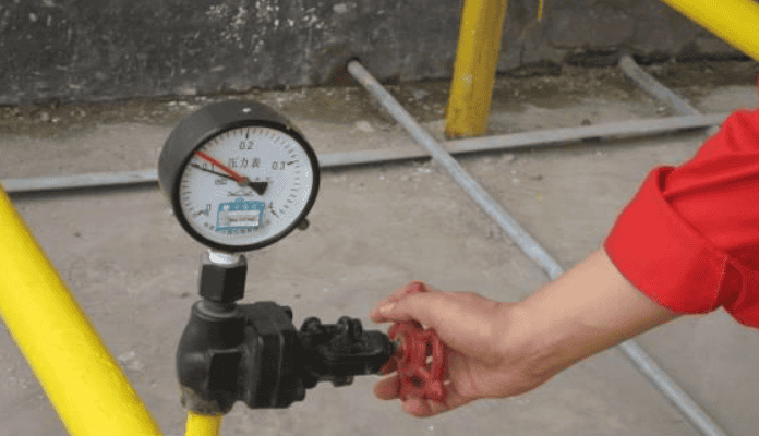
For a refresher on the older mechanical instrument the transmitter replaces, see Pressure Gauge Parts: 12 Components and What They Do.
Four Ways “Pressure Transmitter Types” Gets Used
The phrase pressure transmitter types sounds like one question, but on a working day in a process plant it has four answers. The same words mean four different things to four different engineers.
A spec writer drafting an instrument datasheet uses type to mean the measurement reference, asking whether the device reads against atmosphere, against vacuum, or as a difference between two ports. That choice goes in line one of the datasheet and decides whether the loop ends up correct, off by 1 atm, or impossible to interpret on a windy day at altitude.
A purchasing engineer comparing OEM cells uses type to mean the sensing technology: piezoresistive silicon, ceramic capacitive, sapphire-on-insulator, or MEMS. That choice decides accuracy class, temperature window, and how long the sensor will hold its zero before the technician revisits it.
A drafter on a P&ID uses type to mean output protocol (4-20 mA, HART smart, Modbus RTU, or wireless), because the symbol bubble and the cable count both follow from it.
And a project lead reading a hazardous-area drawing uses type to mean certification class (Ex i, Ex d, sanitary 3-A, or general purpose), because that one decides whether the device is even allowed in the room.
Four engineers, four different things called type. The rest of this guide walks each axis in turn, then puts them back together so a single working datasheet line (gauge / capacitive / 4-20 mA HART / Ex i, IP65, 316L wetted parts) reads cleanly to all four readers.
Anatomy: What Counts as “a Type”?
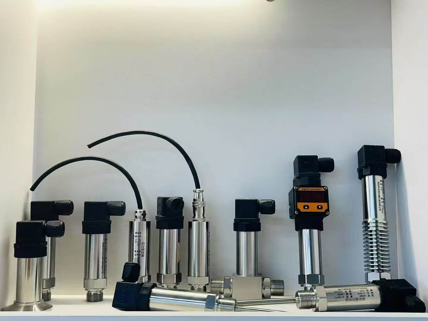
Before we get to the four classification axes, a quick anatomy check makes the rest of the pillar easier to follow. Every industrial pressure transmitter, regardless of brand, breaks into four functional blocks, and each block governs one of the type axes above.
The process connection decides the reference axis. A gauge-reference port has one process side and one atmospheric breather; an absolute-reference port has one process side and a sealed vacuum reference chamber; a DP cell has two process ports and a diaphragm between them.
The sensor cell decides the sensing-technology axis. The cell is where pressure becomes an electrical change: strain in piezoresistive silicon, gap change in a capacitive cell, light deflection in a sapphire cell, or membrane deflection in a MEMS chip. Two transmitters that look identical from the outside can have completely different drift behavior because their cells are different.
The signal conditioner sits inside the housing and decides the output axis. It converts the cell’s millivolt-scale signal into a 4-20 mA loop current, a HART digital overlay, a Modbus telegram, or a wireless burst.
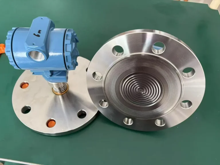
The housing decides the certification axis. The same cell can ship inside a die-cast aluminum Ex d enclosure, a polished 316L sanitary head, or a small plastic OEM shell, and each one carries different paperwork and different installation rules.
Across the next four sections we walk these axes one by one, and in the Type Combinations by Service section we put them back together as a single 12-row service map.
Types by Pressure Reference
Reference is the first column on most spec sheets, and it is also where the most expensive single mistake happens. The five common references are gauge, sealed gauge, absolute, differential, and multivariable, plus remote seal as a process-connection variation that often ships as its own product line. If you are new to the PSI labelling conventions on those datasheets, the PSIA vs PSIG vs PSI cheat sheet decodes all five suffix variants and the conversion math in one place.
Gauge pressure (G) measures the process against the local atmosphere through a small breather port on the back of the housing. A gauge transmitter on a city-water pipe reads zero when the water main is open to atmosphere, regardless of altitude or weather. The HM20 general-purpose pressure transmitter and the HM23 HVAC-R compressor unit are typical gauge instruments in our line.
Sealed gauge (SG) looks like gauge but the breather is replaced by a sealed reference chamber filled at one specified ambient pressure, usually 1 atm. Sealed-gauge instruments are used where the breather would be a contamination risk: submersibles, washdown sanitary skids, or outdoor units in dusty service. The trade-off is a small bias error if the reference chamber’s filled pressure no longer matches local atmosphere; for ground-level sites this is negligible, for mountain installations it matters.
Absolute pressure (A) measures against a sealed evacuated chamber, so the reading is independent of atmosphere. Absolute is the right reference for vapor-pressure work, vacuum systems, and any application where the variable being controlled must hold steady through weather changes. The HE27 vacuum and absolute pressure sensor is the OEM cell our customers reach for here. We have a dedicated absolute vs gauge primer covering the boundary cases (where atmospheric pressure variation is small enough that gauge and absolute readings overlap within roughly 5 percent across most weather) and the sealed-gauge trap in more detail.
Differential pressure (DP) has two process ports, high (HP) and low (LP), and reads only the difference. DP transmitters are the workhorse of flow measurement across orifice plates, level measurement on pressurized tanks, and filter-clog detection: three uses that have nothing to do with each other but all live on the same cell. Our HM3051 smart DP transmitter and the older HM31 capacitive cell cover this segment, with the HM30 micro-DP variant for low-span work. The longer story is in the DP working principle guide.
Multivariable is a DP cell with a static-pressure tap and a temperature input, used in compensated mass-flow measurement on natural gas and steam loops. It is not a third sensor; it is one sensor solving three equations. Multivariables are over-spec for plain DP work, so engineers reach for them only when the loop genuinely needs P, ΔP, and T together.
Remote seal is a process-connection variation rather than a fundamentally different reference. The cell stays gauge or DP, but the wetted membrane is moved away on a flexible capillary so the cell itself never touches the process. Remote seals are how sanitary, high-temperature, or crystallizing service gets a clean pressure reading. The HM70 sanitary flat-membrane unit is our standard for food and pharma work, and the flush-mount transducer line covers similar high-fouling service.
For the math that connects gauge, sealed-gauge, and absolute references — the equation that turns a field reading into an absolute value, with three worked examples — see our gauge pressure formula guide, and the inverse rearrangement P_abs = P_gauge + P_atm — with altitude correction and a hydrostatic worked example — in the absolute pressure formula guide.
Types by Sensing Technology
The sensor cell is where the real engineering decision lives. The reference axis is mostly geometry, but the sensing technology decides how much accuracy you keep in service, how the cell behaves at temperature extremes, and how long it stays calibrated.
Accuracy across global product literature is expressed in the same way: percent of span, with five typical class steps of 0.075, 0.1, 0.2, 0.5, and 1.0. Different regions reference different documents for the test method behind those numbers — the IEC 61298 family is the international touchpoint, ANSI/ISA conventions are common across North America, the EN 837 family is widely used across Europe, and China references GB/T 28474-2012 for performance evaluation. The percent-of-span numbers cross-map directly between them. Verification of zero drift, repeatability, and hysteresis is handled in the calibration lab under the local metrology regulation (in China, JJG 882-2019).
The four sensing technologies engineers actually pick between, plus one niche, work as follows.
| Sensing tech | Working principle | Accuracy class | Max temp at cell | Span turndown | Common service | HMK example |
|---|---|---|---|---|---|---|
| Piezoresistive silicon | Strain changes the resistance of doped silicon traces on a diffused diaphragm | 0.5 to 1.0 | ~120 °C wetted | 5:1 | Hydraulic, OEM, water | HM20, HM24 |
| Ceramic / metal capacitive | Pressure flexes a diaphragm and changes the gap between two conductive plates | 0.075 to 0.2 | ~150 °C wetted | 100:1 (smart) | Refinery, DP loops, sanitary | HM3051, HM50, HE26 |
| Sapphire / SOI | Strain in a sapphire-on-insulator wafer changes resistance; the wafer survives where silicon yields | 0.075 to 0.2 | 250 to 400 °C with seal | 50:1 | Steam, high-T process | HM28, HE28 |
| MEMS | Miniaturized piezo or capacitive element on a single chip, batch-fabricated | 0.5 to 1.0 (0.25 high-end) | ~85 °C silicon limit | 5:1 | Automotive OEM, embedded | HM12, HM12-UC1, HM12-UC2, HM12-UC7 |
| Resonant | A vibrating element shifts frequency under strain; frequency is counted directly | 0.04 to 0.075 (lab grade) | ~150 °C | 200:1 | Custody transfer | (niche, not in HMK lineup) |
Piezoresistive silicon is the cheapest, most common cell in the world and the right answer for most general-purpose loops below 120 °C with non-corrosive media. For multi-year service the long-term stability line on the datasheet (a percent-of-span value the manufacturer commits to over a stated interval) is the number to track; well-built piezoresistive cells stay within their rated stability spec for typical service. Where it falls down is high temperature, high media corrosion, and applications that need accuracy classes tighter than 0.2; once you cross any of those lines you usually move to capacitive or sapphire.
Capacitive is the workhorse of refinery DP and high-accuracy gauge loops. The cell has higher initial complexity than piezo (pressure-to-capacitance conversion is more delicate), but in service it holds its zero better and tolerates wider temperature swings with electronic compensation. Smart capacitive cells routinely deliver 100:1 turndown, which means one transmitter can re-range from 0–10 bar down to 0–0.1 bar without recalibration: a major lifecycle advantage, and one of the reasons HART-capable capacitive cells like the HM3051 dominate process plants.
Sapphire-on-insulator is the answer for high-temperature service. Sapphire stays elastic where silicon plastic-deforms, so wetted temperatures of 250 °C to 400 °C are reachable with the right seal stack. Sapphire cells run a higher initial-complexity tier than piezo and a similar one to capacitive, but they are usually the only path forward in steam-line and hot-process work. Our high-temperature pressure transducer guide walks through the four common methods of getting to 2192 °F (1200 °C) process, mostly via thermal-isolation hardware around a sapphire core.
MEMS is the OEM-volume technology: small, batch-fabricated, low-cost-per-unit. The HM12-UC1, HM12-UC2, and HM12-UC7 German OEM line are MEMS cells we ship to industrial customers in volume. MEMS lives in automotive, white goods, consumer, and embedded industrial. It does not belong in chemically aggressive process service or on hot-side refinery loops; the cell limits show up around 85 °C silicon and the wetted parts are usually unsuitable for corrosive media without an isolating diaphragm.
Resonant cells exist mostly for custody-transfer gas metering, where 0.04 percent accuracy is the regulatory floor. They are interesting to engineers but rarely a competitive choice outside that niche, because the cell is more expensive to build and most loops cannot use the extra accuracy. We do not stock a resonant variant in the HMK line.
For a deeper two-way comparison, see the piezoresistive vs capacitive primer, which is the cluster article underneath this section.
Types by Output and Communication Protocol
Once the cell has a millivolt signal, the signal conditioner is what turns that into something the control system can read. Four output classes cover almost every modern industrial transmitter.
4-20 mA analog is the oldest standard still in serious use, codified historically by ISA and now documented under IEC 60381-1. Two wires carry both power and signal, the loop is intrinsically diagnostic (a broken wire reads zero, not 4 mA), and any DCS card built since the 1970s will accept it. We cover the wiring carefully in the 4-20 mA pressure transmitter wiring guide, which walks the 2-, 3-, and 4-wire variants. For most basic loops that do not need configuration changes after installation, 4-20 mA is still the right answer.
HART (Highway Addressable Remote Transducer) overlays a digital signal on top of the same 4-20 mA wires, letting a handheld communicator or asset-management software read the cell’s diagnostics, change span, and pull the unit’s tag information without touching the loop. HART 7 adds wireless variants (WirelessHART) and longer-frame digital messaging. Almost every modern smart pressure transmitter, including the HM3051, ships with HART as standard. The HART vs 4-20 mA comparison covers the trade-offs in detail.
Modbus RTU over RS-485 is the open-standard industrial digital protocol and is the right answer for plants standardizing on Modbus PLC backbones, especially in water treatment, building automation, and small skid OEM work. It is daisy-chainable, addressable, and cheap to wire, but does not carry power on the same pair. Modbus pressure transmitters like the HM29 digital intelligent cell sit alongside the HM3051 in our smart lineup.
Wireless covers two classes: long-range industrial like LoRa and short-range mesh like Bluetooth or Zigbee. Wireless is the right answer where running cable is uneconomical: tank-farm monitoring, scattered HVAC building automation, retrofit pumping skids, and remote pipeline pressure points. The HM200 wireless pressure sensor on LoRa, the HM200F Bluetooth variant, and the HL10A LoRa gateway form a working stack we deploy in tank-farm monitoring projects.
A working transmitter usually offers one primary output, sometimes two. For example, a smart cell can run 4-20 mA + HART at once, or output 4-20 mA + Modbus on different terminals. The selection comes back to what the host system is asking for and whether anyone will need to touch the device after commissioning.
Types by Certification and Housing
The fourth axis is the one most often forgotten in early spec drafts and the one most likely to fail a final pre-commissioning audit. Certification governs whether the device can legally and safely operate in a given environment. Five common categories cover most industrial work.
Intrinsic safety (Ex i) limits the energy that can reach the cell to below the ignition threshold of the surrounding atmosphere, so the device is safe even in a fault. Ex i is the dominant approach in petrochemical Zone 0 and Zone 1 areas (the highest-hazard locations, where flammable atmospheres are continuously or frequently present), and is also accepted in Zone 2 (where the hazard is less frequent), because it allows live work and replaces the heavy enclosure with safety barriers in the cabinet. The intrinsically safe pressure transmitter selection guide and the Ex i entity-parameter validator tool walk the wiring math in depth.
Explosion-proof / flameproof (Ex d) uses a heavy enclosure that contains any internal explosion and prevents flame propagation to the surrounding atmosphere. Ex d is favored in older refinery installations, in field-mount transmitter standards in certain countries, and in services where the cell must survive a brief external fire. The HM60 explosion-proof transmitter and the HE60 OEM cell are typical Ex d builds in our line.
Ingress protection (IP65 / IP67 / IP68) is the dust-and-water rating governed by IEC 60529. IP65 is rainproof, IP67 survives temporary immersion to 1 m, IP68 survives continuous submersion at a manufacturer-specified depth. Submersible level transmitters like the HM21 line operate at IP68 by definition; HVAC field instruments usually settle at IP65; outdoor industrial transmitters run IP67 as a typical baseline.
Sanitary (3-A, EHEDG) governs food, beverage, dairy, and pharmaceutical service. Sanitary instruments use polished 316L wetted parts (typically Ra ≤ 0.8 µm), tri-clamp or aseptic process connections, and crevice-free seal arrangements that pass clean-in-place and steam-in-place cycles without dead-leg contamination. Our HM70 sanitary flat-membrane unit covers this segment.
Region-specific add-ons. Most regions layer a national or sector certification on top of ATEX or IECEx rather than replacing them: cFMus and cULus across North America, INMETRO in Brazil, KCs in South Korea, EAC across the Eurasian Economic Union, and CCC plus large-EPC internal procurement specs in China. These are usually additive, not substitutional, so the typical workflow is to specify ATEX/IECEx as the base and then verify the destination market’s add-on layer before the order goes out. Missing the add-on is a common late-stage rework trigger.
A pre-commissioning audit usually walks the four axes one final time (reference, sensing, output, certification) against the panel drawings and the wetted-parts spec. Catching a certification mismatch at that stage is recoverable; catching it after the cell is already wired in a Zone 1 area is not.
Type Combinations by Service: 12 Worked Examples
The four axes only become useful when they are read together. The table below shows twelve common service scenarios and the type combination engineers typically reach for in each. The HMK SKU listed in the last column is one example matching the combination; equivalents from other manufacturers fit the same row.
| # | Service description | Reference | Sensing | Output | Cert / housing | Example HMK SKU |
|---|---|---|---|---|---|---|
| 1 | Vented water tank, 0–10 bar, indoor | Gauge | Piezoresistive | 4-20 mA | IP65, general purpose | HM20 |
| 2 | Vacuum chamber, 0 to −1 bar absolute | Absolute | Capacitive (vacuum-grade) | 4-20 mA + HART | IP65 | HE27 |
| 3 | Heavy-oil DP flow on an orifice run | DP | Capacitive (high-overpressure) | 4-20 mA + HART | Ex i, IP67 | HM3051 |
| 4 | Saturated steam line, 250 °C wetted | Gauge | Sapphire-on-insulator | 4-20 mA | IP67 | HM28 |
| 5 | Food-grade CIP/SIP skid, 3-A required | Gauge (remote seal) | Capacitive (sanitary) | 4-20 mA | 3-A sanitary, 316L | HM70 |
| 6 | Automotive OEM volume production | Gauge | MEMS | 0.5–4.5 V or I²C | OEM, plastic shell | HM12-UC2 |
| 7 | Methanol storage tank in a Zone 1 area | Gauge | Capacitive | 4-20 mA + HART | Ex i, IP66 | HM50 |
| 8 | Cleanroom 0–100 mbar low pressure | DP / micro-DP | Capacitive (low-span) | 4-20 mA | IP65 | HM30 (or HE30 OEM) |
| 9 | Hydraulic skid, 0–350 bar shock loads | Gauge | Sapphire | 4-20 mA | IP67 | HM28 |
| 10 | Submersible deep-well water level | Sealed gauge | Piezoresistive (submersible) | 4-20 mA | IP68 | HM21 |
| 11 | Semiconductor process gas line, harsh-environment | Absolute | Sapphire | 4-20 mA + HART | 316L wetted, harsh-env | HE28 (specify electropolished, EP, wetted parts as a custom-spec option) |
| 12 | Tank-farm wireless monitoring | Gauge | Piezoresistive | LoRa wireless | IP67, battery-pack | HM200 + HL10A gateway |
Row 3 deserves a closer look because the case is well documented across Chinese refineries. Heavy-oil DP loops on coker and atmospheric distillation units historically ran piezoresistive cells, and Sinopec field reports we have on file note that the zero point typically drifted by a noticeable fraction every six to nine months under the cyclic thermal load. After upgrade to capacitive cells with diaphragm-seal isolation, the same loops moved to a recalibration interval measured in years rather than months. The information gain here is the lifecycle pattern, not a single number; the qualitative shape (piezo loses zero faster than capacitive on hot-cyclic service) is what informs row 3.
The full pillar logic is “pick a row that resembles your service, then verify the four axes against the actual datasheet line.” None of the rows is a recommendation; they are starting points for a real spec walkthrough.
For deeper application notes by axis, see the low-pressure transducer guide, the intrinsically safe transmitter selection page, and the DP level measurement primer.
6-Step Selection Workflow
A practical workflow for spec writers walks the four axes plus three engineering decisions, in this order.
Step 1. Identify what you are measuring. Tank head, pipe pressure, flow ΔP, vacuum level, or compensated mass-flow. This decides the reference axis (gauge / sealed / absolute / DP / multivariable / remote seal).
Step 2. Ask whether atmospheric independence matters. If the variable must hold steady across weather changes, altitude shifts, or vacuum service, the reference is absolute. Otherwise gauge or sealed-gauge does the job and is cheaper to build. The absolute vs gauge primer covers the boundary cases.
Step 3. Set operating temperature and media compatibility. Wetted parts and cell limits decide the sensing-technology axis. Below 120 °C and clean media: piezoresistive. Wider temperature, better drift, or higher accuracy class needed: capacitive. Above 150 °C wetted, or cyclic high-temperature service: sapphire. OEM volume on small low-cost units: MEMS.
Step 4. Pick the accuracy class. Map the loop’s required accuracy onto GB/T 28474-2012’s five-class system (0.075 / 0.1 / 0.2 / 0.5 / 1.0). For most plant-floor work, 0.1 to 0.5 is the working range; 0.075 is custody-transfer territory; 1.0 is fine for indication-only loops where the controller does not need tight feedback. JJG 882-2019 sets the verification protocol the chosen class must survive in the calibration lab.
Step 5. Decide the output protocol. Plain analog: 4-20 mA. Smart with diagnostics: HART. Modbus PLC plant: RS-485. Hard-to-cable point: wireless. The host system’s input card list is usually the gating constraint; verify before specifying a protocol the DCS cannot read.
Step 6. Confirm certification and process connection. Pick the housing axis from four common categories: Ex i for hazardous area with live work, Ex d for hazardous area without live work, 3-A or EHEDG for sanitary service, and IP67 as a sensible outdoor baseline. Then verify the destination market’s regional add-on layer on top of ATEX or IECEx (for example, cFMus or cULus across North America, or whichever scheme governs the project location). Missing the regional layer is a common cause of pre-commissioning rework. Process connection (NPT, G, M20, or sanitary tri-clamp) follows the piping standard on the existing P&ID; the NPT vs G thread guide walks the common mismatches. The bubble convention used to draw that transmitter on the same drawing is decoded in our P&ID transmitter symbol guide.
Six steps, four axes plus three decisions, and the spec line writes itself.
Common Selection Mistakes from the Field
Four selection mistakes show up across the projects we get called in to review.
Mistake 1. Specifying gauge where sealed-gauge or absolute is required. A vapor-pressure loop, an evaporator pressure controller, or any loop sensitive to barometric drift will read incorrectly with a vented gauge instrument once the weather changes. The fix is upstream: ask whether the controlled variable is a true pressure (gauge) or a vapor reading (absolute) before the type is locked.
Mistake 2. Putting piezoresistive cells on hot-cyclic steam service. On hot-cyclic 180 °C steam-trace service, we have seen piezoresistive transmitters look fine for several months and then begin losing zero; within a year the loop is unsuitable for closed-loop control and useful only as an indication. Sapphire is the right answer for hot-cyclic service, and the high-temperature transducer guide walks four methods of getting there.
Mistake 3. Putting MEMS cells on aggressive chemical service. MEMS cells without an isolating diaphragm are not chemically rated for refinery-grade media, and the cost saving disappears the first time a wetted part fails. The correct path is ceramic capacitive (HE26, HM50) or sapphire (HM28, HE28) with the appropriate wetted material.
Mistake 4. Treating multivariable as a one-instrument-does-all solution. Multivariable transmitters are designed for compensated mass-flow on natural gas and steam loops where the customer genuinely needs P, ΔP, and T together. On a plain DP flow loop, a multivariable is over-spec, harder to commission, and harder to support. A standard smart DP cell (HM3051 or equivalent) does the job better.
There are other mistakes worth a longer write-up (forgetting the certification axis until pre-commissioning, mixing NPT and G thread in the same skid, not checking the host system’s protocol support before specifying HART), and we cover those in their dedicated articles.
Common Type Patterns by Industry
Engineers in different industries reach for different type combinations because the dominant constraints are different.
Petroleum and chemical processing. The dominant constraint is hazardous-area certification and high-temperature service. Common patterns: gauge or DP, capacitive or sapphire, 4-20 mA + HART, Ex i housing. The HM50 and HM3051 cover much of this segment.
Food, beverage, and pharmaceutical. The dominant constraint is sanitary cleanability and CIP/SIP cycles. Common patterns: gauge with remote seal, capacitive cell, 4-20 mA, 3-A sanitary 316L wetted parts. The HM70 covers this segment.
HVAC, building automation, and cleanrooms. The dominant constraints are low-pressure span and Modbus or BACnet protocol. Common patterns: DP or low-pressure gauge, capacitive cell, Modbus RS-485 or 4-20 mA, IP65 housing. The HM23 and HM30 cover this segment.
Power generation and steam systems. The dominant constraint is high-temperature steam service and long unattended runtime. Common patterns: gauge or DP, sapphire cell, 4-20 mA + HART, Ex i for boiler-house Zone 2 areas. The HM28 covers the hot-side cells.
Semiconductor and harsh-environment process gas. The dominant constraints are absolute reference and clean wetted parts. Common patterns: absolute, sapphire cell, 4-20 mA + HART, 316L wetted with electropolished finish specified as needed. The HE27 absolute and HE28 sapphire OEM cells cover this segment as base products; for ultra-clean semiconductor fab service, an electropolished or specially finished wetted part needs to be specified as a custom option.
Water treatment, municipal, and submersible. The dominant constraints are submersibility and cable run length. Common patterns: sealed-gauge, piezoresistive cell, 4-20 mA, IP68 submersible housing. The HM21 line covers this segment.
Hydraulic and mobile equipment. The dominant constraints are shock loading and high pressure. (Note: heavy-duty static-rated transmitters survive shock impacts but cannot capture the wavefront itself — for microsecond-scale dynamic measurement of shock waves, water-hammer pulses, and blast events, use a piezoresistive dynamic sensor such as the CYG405 in the 300-800 kPa low-pressure regime or the CYG401 for higher pressures.) Common patterns: gauge, sapphire or piezoresistive heavy-duty, 4-20 mA, IP67. The HM28 covers this segment.
These patterns are starting points; the four-axis spec walk above is what locks the actual line.
Related reading: How to Read a Pressure Gauge Correctly Every Time — analog dial basics, dual-scale traps, tell-tale needles, and 5-step calibration check from the field. For the upstream definition primer on what a temperature gauge is and the five sensing types, see Temperature Gauge: Definition, 5 Types, and Selection Guide.
FAQ
How many types of pressure transmitter are there?
Five reference types (gauge, sealed gauge, absolute, differential, multivariable, with remote seal as a process-connection variation), four common sensing technologies (piezoresistive, capacitive, sapphire, MEMS, plus resonant as a niche), four output protocols (4-20 mA, HART, Modbus, wireless), and several certification classes (Ex i, Ex d, IP, sanitary). A single transmitter is one combination of all four axes.
Which type is most accurate?
Capacitive and sapphire cells reach 0.075 to 0.1 percent of span under the GB/T 28474 framework. Piezoresistive cells typically run 0.5 percent. Resonant cells exist at 0.04 percent for custody-transfer gas metering but are uncommon outside that niche.
What is the difference between a pressure sensor, transducer, and transmitter?
The sensor is the cell only, the transducer is the cell plus signal conditioning, and the transmitter is the full unit with calibrated output ready to wire to a control system. The pressure sensor vs transducer vs transmitter primer walks the boundaries in detail.
Which type is best for high temperature?
Sapphire-on-insulator cells handle wetted temperatures from about 250 °C to 400 °C, depending on the seal stack. Above that, thermal-isolation hardware (cooling fins, capillary remote seals) is added in front of the cell. Piezoresistive cells fail above about 120 °C wetted; capacitive cells reach about 150 °C.
Smart versus analog pressure transmitter, which to pick?
Smart (HART) costs slightly more in initial cost but pays back the first time someone needs to re-range or pull diagnostics. For loops that will never be reconfigured after commissioning, plain 4-20 mA is fine. For any loop where a technician will revisit the device, smart is the better engineering choice.
Can one transmitter measure multiple pressure types?
Generally no. A single device is built for one reference (gauge, absolute, or DP). Multivariable transmitters are the exception, combining DP, static pressure, and temperature in one unit specifically for compensated mass-flow service.
Related reading: For the digital LCD reference path applied to lube oil monitoring, see our electric oil pressure gauge guide. For the upstream gauge that feeds a regulator on a pneumatic, hydraulic, or instrument-air main, see Supply Pressure Gauge: What It Does and Where to Spec It. For the HVAC duct field workflow — probe placement, acceptable TESP ranges, and instrument class selection — see our How to Measure Static Pressure in HVAC guide.
For the analogous selection question on temperature loops, see our temperature element vs transmitter guide; for the mechanical dial side of the same picture, see our bimetallic, filled, and gas-actuated temperature gauge guide.
For non-process applications of negative-reading transmitters — HVAC duct, cleanroom airlock, hospital isolation, refrigeration suction, boiler draft, automotive intake — see Negative Pressure Gauge Applications, which maps typical readings and instrument selection across all six domains.
For the mechanical gauge accuracy ladder (Cl 0.1 through 4.0) and how ASME B40.100, EN 837-1, and GB/T 1226-2017 map onto each other, see Pressure Gauge Accuracy Class: 0.1 to 4.0 Selection Guide.
See also: the full vacuum measurement procedure for the bench-to-publication six-step workflow.
Where to go next. Two cluster reads dive deeper than this pillar: the piezoresistive vs capacitive primer covers the sensing-technology axis in detail, and the absolute vs gauge primer covers the reference axis. For side-by-side spec comparison across the HMK lineup, the pressure sensors and transmitters category page lists every product with its datasheet linked from each entry.
Related reading: Once you have narrowed the transmitter type, see how each maps to actual deployment in pressure transducer applications by industry — hydraulic, HVAC, oil and gas, sanitary, and lab service.