Intrinsically Safe Pressure Transmitter: Ex i Selection & Spec Guide
A pressure transmitter datasheet for a hazardous-area service line carries three to seven Ex certifications and a string of letters that decodes the protection method, gas group, temperature class, and Equipment Protection Level. This guide unpacks what intrinsic safety (Ex i) means for a pressure transmitter, and when it wins over flameproof (Ex d). It also walks through how to read ATEX, IECEx, GB 3836, and the rest of the global certification stack, and which entity parameters drive whether a spec ships or goes back for revision.
Intrinsic safety is one of three protection concepts. For the full picture of how area classification drives that choice, see our hazardous location pressure transmitter selection guide.
What “Intrinsically Safe” Means for a Pressure Transmitter
Two protection methods own the hazardous-area instrumentation market, and they solve the ignition problem in opposite directions. Intrinsic safety (Ex i) prevents the spark by limiting the energy in the loop. Flameproof (Ex d) accepts that a spark may happen and contains the resulting flame inside a heavy housing. For pressure transmitters specifically, devices that already run on milliamp-class signals (see pressure transmitter operating principle for the loop math), Ex i is the natural fit, and the rest of this guide assumes that starting point.
Intrinsic safety works by capping the voltage, current, and stored energy that can reach the field side. A Zener barrier (passive, single-channel, plant-earth referenced) or a galvanic isolator (active, transformer-coupled, no earth dependency) sits in the safe area between the DCS and the transmitter. The barrier clamps the loop so a single fault, such as a short circuit, broken cable, or exposed conductor in a flammable atmosphere, cannot release enough energy to ignite the worst-case gas mixture in the rated zone.
IEC 60079-11 defines three subcategories of intrinsic safety, each tied to a fault tolerance and an Equipment Protection Level (EPL):
- Ex ia (EPL Ga): safe with two simultaneous faults; rated for Zone 0 (continuous flammable atmosphere)
- Ex ib (EPL Gb): safe with one fault; rated for Zone 1 (likely flammable atmosphere)
- Ex ic (EPL Gc): safe in normal operation; rated for Zone 2 (rare flammable atmosphere)
A transmitter rated Ex ia IIC T4 Ga can serve any zone from 0 to 2 in any gas group through methane down to hydrogen, with a maximum surface temperature of 135 °C.
A note for buyers reviewing legacy Asian instrumentation: China’s intrinsic-safety standard runs from GB 3836.4-1983, originally modeled on IEC 79-11, through three revisions to the current GB 3836.4-2021. Modern GB 3836.4 mirrors IEC 60079-11 clause-for-clause, but older plants still hold instruments carrying only the 1983 or 2010 markings. Those units are valid for the original installation but carry less explicit Ex ia/ib/ic subcategory language, which can cause friction during audits referencing the current IEC framework. The next section unpacks how Ex i contrasts with Ex d, and where each protection method actually wins on installed cost and live maintenance.
How Ex i Differs From Ex d (Flameproof / Explosion-Proof)
Ex i and Ex d both prevent gas explosions in classified areas, but their cost profile, footprint, and maintenance access diverge sharply. Ex i is the lighter approach: a small enclosure, thin instrumentation cable, and a certified barrier sitting in the safe area. The process port itself follows the regional thread standard — see NPT vs BSP/G thread guide if your project spans North America and EMEA. Ex d is the heavier approach: thick-walled flameproof housing, threaded conduit running into the field, and no live-work allowed. The table below puts both methods side-by-side on the eight engineering parameters most plant designers actually weigh during specification.
| Parameter | Ex i (Intrinsic Safety) | Ex d (Flameproof) |
|---|---|---|
| Protection method | Energy limited at the source | Explosion contained inside housing |
| Field-side energy | < 1.3 W typical | Unrestricted within rating |
| Live maintenance | Permitted with no hot-work permit | Hot-work permit + power isolation required |
| Cable type | Light, blue-jacketed (color-coded) | Armored or rigid metal conduit |
| Conduit scope | Standard armored cable run | RMC + sealing fittings at every junction |
| Housing weight | 0.5–1.5 kg typical | 4–10 kg typical |
| Footprint | Compact, mountable on small process taps | Bulky, needs reinforced bracketry |
| Best for | Pressure / temperature / DP transmitters in Zone 0/1/2 | Solenoids, motors, high-power loads in Zone 1/2 |
For a 4-20 mA pressure transmitter, the math almost always favors Ex i. The transmitter itself draws 4-22 mA at 24 VDC, well below the energy ceiling that drives the Ex d housing-weight penalty. The Ex i barrier in the safe area is light, single-channel, and adds one termination block to the rack; the rest of the loop runs in standard armored cable. The Ex d alternative carries thick-walled cast aluminum or steel housings, double-pole sealed glands, and rigid conduit from cable tray to device. On Sinopec atmospheric distillation rebuilds, conduit and sealing-fitting scope on Ex d transmitter loops typically matches the scope of the transmitters themselves; switching to Ex i collapses that field scope to a single armored cable run.
Ex d still earns its place on power-hungry final elements such as trip valves and motor starters. For the loops a pressure engineer signs off on, Ex i is the structural default. See the explosion-proof pressure transmitter (Ex d) variant when site standards force the choice.
Hazardous Area Zones and Where Ex i Fits
Hazardous areas are classified by how often a flammable atmosphere is present, not by what gas sits in the pipe. IEC 60079-10-1 splits gas areas into three zones; IEC 60079-10-2 mirrors the structure for combustible dusts. NEC 500 maps roughly into the same hierarchy under the Class/Division system used in North America. Each zone is then paired with a gas group (IIA propane, IIB ethylene, IIC hydrogen/acetylene) and a temperature class (T1 through T6, where T6 caps the maximum surface temperature at 85 °C). GB 3836-2021 in China and EAEU TR CU 012 in Russia and Kazakhstan use the same zone definitions, which makes the IEC framework portable across most of HMK’s deployment markets.
The mapping below pairs each zone with the Ex i subcategory that satisfies it; that choice cascades into barrier selection, cable routing, and certified equipment scope on every loop.
| Zone (IEC 60079-10) | Frequency of flammable atmosphere | Ex i subcategory needed | NEC 500 equivalent |
|---|---|---|---|
| Zone 0 | Continuous or for long periods | Ex ia (Ga) | Class I Div 1 (continuous) |
| Zone 1 | Likely under normal operation | Ex ia or Ex ib (Ga / Gb) | Class I Div 1 (intermittent) |
| Zone 2 | Rare and only short term | Ex ia, ib, or ic | Class I Div 2 |
| Zone 20 | Continuous combustible dust cloud | Ex iaD (Da) | Class II Div 1 |
| Zone 21 | Likely combustible dust cloud | Ex iaD or ibD (Da / Db) | Class II Div 1 |
| Zone 22 | Rare, short-term dust cloud | Any iD subcategory | Class II Div 2 |
On a Sinopec atmospheric distillation unit, zoning runs head to tail. The column overhead and receiver vapor space carry continuous hydrocarbon vapor and classify as Zone 0. Pump suction lines and sample points sit in Zone 1. The pump house floor and outdoor pipe rack drop to Zone 2. A hydrotreater feed line into the reactor classifies as Zone 1, yet project specs commonly pick Ex ia to keep one fault-tolerance margin against hydrogen ingress at the diffuser ring. Downstream tank-farm Zone 2 instruments are then allowed to run Ex ic, which recovers some of that margin’s barrier and cable scope.
A second worked example: at CNPC’s Daqing oil and gas storage terminal, the LNG receiving line carries cryogenic methane vapor through a Zone 1 piperack into a Zone 0 tank dome. Field practice picks Ex ia IIC T6 Ga for both. The IIC gas group is required because methane vapor in the cryogenic state can locally enrich into IIC-class mixtures near the dome roof. The T6 surface limit (85 °C) covers heat tracing on the impulse line during winter operation. The same Ex ia spec then carries through to the truck-loading bay (Zone 1) for spec consistency across the terminal. Pick the explosion-proof pressure sensor for hazardous areas when an OEM-class form factor is needed in the same zone classifications.
Certification Systems on Ex i Datasheets
A pressure transmitter datasheet usually carries three to seven Ex certifications stacked in one block. Each one entitles the device to enter a specific regulatory market, and most are not mutually interchangeable. ATEX 2014/34/EU is the EU Directive route; IECEx is the international scheme that several national bodies recognize but does not by itself substitute for ATEX inside the EU; UL and FM cover the United States; CSA covers Canada; INMETRO covers Brazil; EAC TR CU 012 covers the Eurasian Economic Union; GB 3836 covers China through the NEPSI conformity body.
| Scheme | Region | Standard family | Issuing / Conformity body | Reciprocal with IECEx? |
|---|---|---|---|---|
| ATEX 2014/34/EU | EU + EFTA | EN 60079-x | Notified Body (TÜV, DEKRA, Sira) | No — separate test report often required |
| IECEx | International (33 member states) | IEC 60079-x | IECEx Certified Body | — |
| UL / FM | United States | UL 60079-x / FM 3600-series | UL Solutions or FM Approvals | No |
| CSA | Canada | CSA C22.2 No. 60079-x | CSA Group | Partial (under UL/CSA mutual) |
| INMETRO | Brazil | ABNT NBR IEC 60079-x | OCP accredited by INMETRO | Yes (with type approval ratification) |
| EAC TR CU 012 | EAEU (RU, KZ, BY, AM, KG) | GOST 31610.x (≈ IEC 60079) | EAC notified body | Yes (TR CU 012/2011) |
| GB 3836 | China | GB 3836.x-2021 | NEPSI (CNEx, Shanghai) | Bilateral via IECEx route |
Reading Ex ia IIC T4 Ga decodes to four parts:
- Ex ia: intrinsic safety with two-fault tolerance
- IIC: gas group covering hydrogen and acetylene
- T4: maximum surface temperature 135 °C
- Ga: Equipment Protection Level suitable for Zone 0
The full string dictates which zone, gas, and temperature service the unit may enter.
Engineers buying Ex i pressure transmitters from Asia-Pacific suppliers run into GB 3836 most often, and the standard deserves a separate read. GB 3836-2021 in its current eight-part form is technically equivalent to IEC 60079, with GB 3836.4 covering intrinsic safety and GB 3836.2 covering flameproof construction. The conformity body NEPSI (the National Supervision and Inspection Center for Explosion Protection in Shanghai) issues certificates that satisfy Chinese plant audits and most ASEAN tender specs. NEPSI does not directly replace ATEX or UL. An EU plant import still needs ATEX; a US plant still needs UL or FM. A NEPSI certificate signals the manufacturer can pass IECEx-equivalent testing, which shortens the IECEx ratification path. Indian, Vietnamese, and Indonesian project specs increasingly accept NEPSI as a baseline credential.
Specifying an Ex i Pressure Transmitter
Once protection method and zone are settled, the spec sheet for an Ex i pressure transmitter has ten line items that drive cost, lead time, and field interchangeability. The list below is the same one HMK product engineering uses on customer quotations, ordered the way an instrument-and-electrical (I&E) lead actually fills out a data sheet.
| Spec line | What to specify | Notes for Ex i |
|---|---|---|
| Pressure range | Min / Max in kPa, bar, or psi | Match rangeability; 10:1 turndown standard |
| Accuracy | ±% of span | 0.1% standard, 0.075% for custody-grade |
| Process connection | G1/2, 1/2-14 NPT, sanitary clamp | Match manifold or manifold-less mounting |
| Output | 4-20 mA passive (2-wire) | Passive loop fits Ex i barriers cleanly |
| Communication | HART 7 / Modbus RTU | Verify barrier bandwidth for HART |
| Wetted material | 316L SS / Hastelloy C-276 / sapphire / ceramic | Pick by media corrosion |
| Power supply | 9–30 VDC through certified barrier | Note Ui / Ii at the barrier output |
| Temperature class | T4 (135 °C) typical; T6 for hydrogen-rich | Tied to gas group |
| Ingress protection | IP66 / IP67 minimum | NEMA 4X common for North America |
| Entity parameters | Ui, Ii, Pi, Ci, Li | Must satisfy the barrier loop calculation |
The last row, entity parameters, is the one most engineers underestimate. Ui (max input voltage), Ii (max input current), and Pi (max input power) are the device’s safety ceilings; Ci (internal capacitance) and Li (internal inductance) are the energy storage the loop must account for. The barrier’s allowable Co and Lo, minus the cable run’s distributed C and L, must remain greater than the transmitter’s Ci and Li, or the Ex i certification is void in that loop.
A practical margin worth adopting: NEPSI-supervised commissioning practice at Chinese metallurgy and petrochemical sites holds 30 percent headroom on the Co minus Ci calculation for cable runs over 200 m, because temperature drift across an Asian summer can shift cable capacitance by up to 10 percent. EN-language datasheets rarely publish this margin guidance, but it is standard practice in commissioning reports filed to NEPSI and increasingly referenced by Indian and Vietnamese audit teams reviewing imported instrumentation.
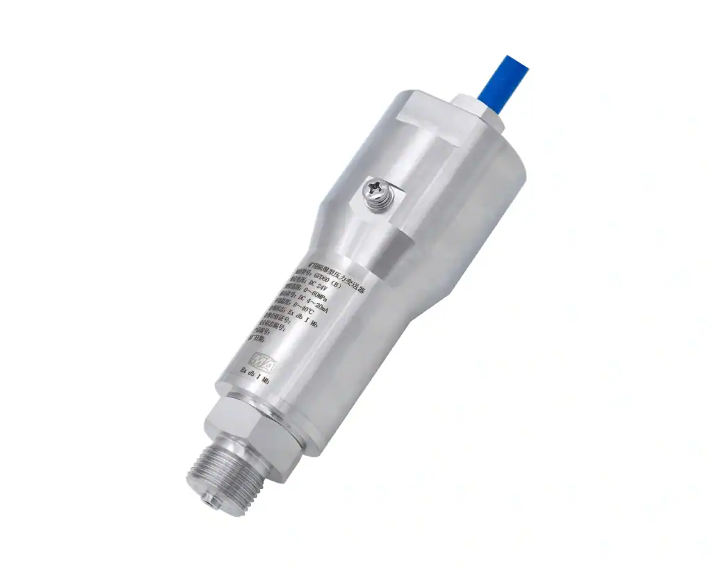
For a worked example, the HMK HM60 sapphire pressure transmitter ships with dual certification: Ex d IIC T6 Ga for the flameproof variant and Ex ia IIC T6 Ga for the intrinsic-safety variant. Range covers -100 kPa to 100 MPa with 4-20 mA passive output and HART 7. Process connections include G1/2, 1/2-14 NPT, and 1-1/4 NPT. See HM60 sapphire pressure transmitter (Ex i / Ex d dual-certified) for full entity parameters. For corrosive Ex i service the HM50 anti-corrosive pressure transmitter carries Hastelloy and PTFE wetted parts; the HM28 sapphire pressure transmitter is the high-pressure Ex i variant in the same series. The companion guides 4-20 mA passive loop wiring and HART on top of 4-20 mA cover barrier placement and bandwidth checks.
Try it interactively: the Ex i Entity Parameter Validator checks all five inequalities for any transmitter / barrier / cable combination, with three HMK presets and the optional 30% NEPSI commissioning margin built in.
Common Field Mistakes With Ex i Installations
Four installation mistakes account for most Ex i loop failures in the field. Each one passes the visual inspection that follows commissioning, and only shows up later as drift, dropouts, or a failed audit.
- Exceeding the entity-parameter envelope. A long instrumentation cable adds enough distributed capacitance to break the Co > Ci + C_cable inequality, and the loop loses certification without anyone noticing on commissioning day.
- Sharing safe-area and hazardous-area conductors. Routing both through the same conduit or terminal box violates IEC 60079-14 segregation rules. Crosstalk and induced voltage are the field symptoms; loss of certification is the audit symptom.
- Bonding the Ex i shield to the plant earth bus. This re-introduces the ground loop the barrier was meant to break. Mill-motor stray currents, VFD harmonics, and welder ground noise all ride in through that single termination choice.
- Using a non-Ex calibrator inside Zone 1 during commissioning. This is a permit violation regardless of how brief the work is. A certified calibrator stays in the safe area; the field side is jumpered out for the duration.
On one Conch Cement raw mill DP measurement loop, an Ex i transmitter showed slow output drift that field staff first blamed on the diaphragm. The root cause was the shield termination: it had been bonded to the plant’s general earth bus instead of a separate single-point intrinsic-safety equipotential earth, which let mill-motor stray current ride into the loop. Splitting the IS shield onto its own earth bus stabilized the reading the same shift — a textbook example of mistake #3 above.
A side note while reading these traps: Ex documentation often switches between “transmitter,” “transducer,” and “sensor” without clean definition. The terminology distinction matters when matching a barrier to a device. See transmitter vs transducer terminology for the field-engineering view.
When Ex d Is the Better Choice
Ex i is the structural default for pressure measurement, but four scenarios push the choice toward Ex d. The decision matrix below the list ties each scenario to a single design driver.
- High-power final elements. Trip valves, motor starters, and large solenoid blocks draw energy that no Ex i barrier can deliver within its entity-parameter ceiling.
- Heavy mechanical environments. High vibration, projectile risk, and frequent impact loads favor a cast Ex d housing over the thin enclosure typical of Ex i hardware.
- Plants on a legacy Ex d standard. Sites standardized on Ex d conduit systems decades ago face a brownfield conversion penalty that outweighs Ex i’s per-loop savings.
- Cabinet-space-constrained retrofits. Limited safe-area racks can lack room for the certified barrier hardware Ex i requires, leaving Ex d as the only path that fits the existing footprint.
| Driver | Ex i wins when | Ex d wins when |
|---|---|---|
| Field-side power | < 1.3 W (transmitters, sensors) | Beyond IS barrier output capacity (solenoids, motors, heaters) |
| Mechanical environment | Indoor process tap, low vibration | Outdoor exposure, high vibration, impact risk |
| Plant heritage | Greenfield or instrument-only retrofit | Existing Ex d conduit standard in service |
| Safe-area space | Cabinet has barrier rack capacity | Limited or fully populated rack |
For the matching HMK product when any of the four scenarios forces Ex d, see the Ex d flameproof pressure transmitter variant — same sapphire cell, different housing, same dual-certification benefit.
FAQ — Ex i Pressure Transmitter Questions
Q1: Is 4-20 mA intrinsically safe?
No, not on its own. A 4-20 mA loop carries enough energy to ignite the worst-case gas mixture under fault. To make it intrinsically safe, terminate the loop through a certified Zener barrier or galvanic isolator that clamps voltage, current, and stored energy to the gas-group entity limits.
Q2: How do you tell if a device is intrinsically safe?
Read the nameplate. An Ex i device carries a code such as Ex ia IIC T4 Ga, an EPL marking (Ga / Gb / Gc), the issuing body (ATEX, IECEx, NEPSI, UL), and a certificate number. Without that block printed on the housing, the device is not certified intrinsically safe.
Q3: What’s the difference between intrinsically safe and non-incendive (Class I Div 2)?
Non-incendive (NI) only avoids ignition energy in normal operation. Ex i must stay non-igniting under fault: Ex ia survives two simultaneous faults, Ex ib survives one. NI is acceptable in Class I Div 2 (Zone 2 equivalent) only; Ex i covers Zone 0 / 1 / 2 depending on subcategory.
Q4: Does Ex i support HART communication?
Yes, with the right barrier. HART superimposes 1200 Hz and 2200 Hz FSK signaling on top of the 4-20 mA carrier. The barrier must be rated for HART pass-through, with allowable loop capacitance (Ci + C_cable + C_barrier) low enough that the HART signal survives at the receiver without distortion.
Q5: Can one barrier serve two Ex i loops?
Single-channel barriers cannot. A multi-channel barrier handles as many loops as it has independent channels, and each channel is rated separately for Uo, Io, Co, and Lo. Doubling two transmitters onto one channel violates the entity calculation; cable and device storage stack, and the loop loses certification.
Q6: Are GB 3836 / NEPSI certificates accepted in EU and US plants?
Not directly. EU imports require an ATEX 2014/34/EU certificate; US plants require UL or FM under the NEC 500 framework. NEPSI alone is not a substitute. However, a NEPSI certificate signals the manufacturer can pass IECEx-equivalent testing, which shortens the path to obtaining ATEX or IECEx ratification.
If a spec line on your data sheet still does not decode cleanly after this read, write to the HMK pressure engineering team. The reply comes from the bench, not from sales.