Piezoresistive vs Capacitive Pressure Sensors: Which Fits Your Application?
Piezoresistive and capacitive cells are the two sensing principles behind almost every process pressure transmitter shipped today. They perform identically on a quiet bench. They diverge the moment the process gets corrosive, the pressure cycles hard, or the ambient climbs past 85 °C. This page sorts them across four engineering constraints that decide the call: accuracy, range, media compatibility, and temperature behaviour. Case data and cell-level spec evidence, not brochure claims.
Whichever sensor element you pick, temperature drift is the next spec to read. See pressure sensor temperature compensation for what zero shift and span shift mean and how passive and active circuits cancel them.
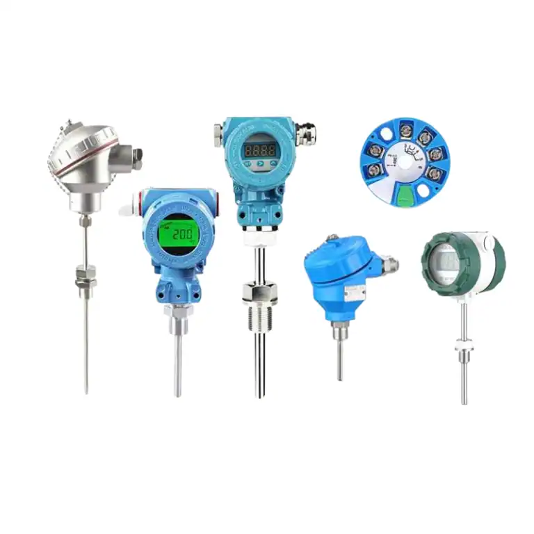
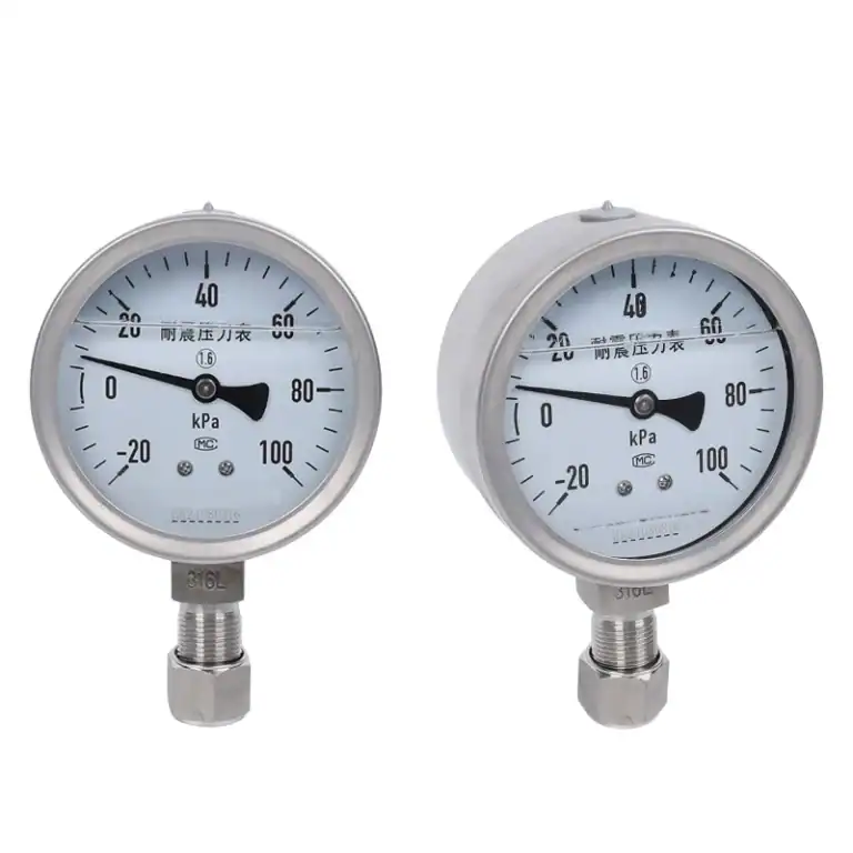
If you are weighing modern semiconductor sensors against an older mechanical Bourdon-tube gauge, the 12 mechanical parts of the dial gauge collapse into a single solid-state element on the digital side.
When the Sensing Principle Actually Matters
Most pressure loops don’t care which cell you pick. A clean medium, full-scale below 4 MPa, ambient 10 to 50 °C, accuracy allowance wider than 0.25% FS — any transmitter on the stores shelf does the job. The HM20 covers that territory.
The sensing principle becomes the deciding variable in four cases: transients above four times FS, HF or chloride service that dissolves 316L, process temperature swinging past 85 °C, and accuracy budgets under 0.1% FS. For everything else, cell technology is a second-order concern. See the sensor, transducer, transmitter page if the terms blur.
The Two Sensing Principles in 60 Seconds
Not to confuse: piezoresistive, piezoelectric, strain gauge. Piezoresistive cells change resistance under strain in doped silicon (DC response, suited for static pressure). Piezoelectric cells generate charge under transient pressure (AC response, no DC capability, dominant in shock and vibration sensors, not industrial transmitters). Foil strain gauges work on the same principle as piezoresistive silicon but with a gauge factor of about 2 instead of 100. This page is about piezoresistive silicon, not the other two.
Piezoresistive — strain in silicon
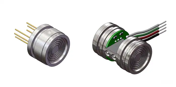
A piezoresistive cell is a silicon diaphragm with four p-type resistors diffused into it as a Wheatstone bridge. Pressure bends the diaphragm. Tensile-side resistors grow, compressive-side resistors shrink, bridge output tracks ΔR/R. Silicon’s gauge factor sits near 100, so the cell hands the ASIC a strong 3 mV/V signal to linearise and temperature-compensate.
Three construction families cover the market. Bulk-etched MEMS is cheap and OEM-grade. Diffused silicon on stainless, built by HE24, takes the process directly. Silicon on sapphire, built by HE28, reaches 260 MPa.
Capacitive — plate gap shift
A capacitive cell is two conductive plates 200–500 micrometres apart. One is the diaphragm. Pressure closes the gap, capacitance rises as ΔC/C₀ ≈ Δd/d₀, and a sigma-delta converter reads the change as digital counts. Starting capacitance is 20–50 pF, full-scale shift under one picofarad.
Oil-filled metal-diaphragm cells, the HM1151 pattern, put thin 316L in front of silicone oil that pressures a ceramic reference. Dry ceramic cells skip the oil: a 99.6% Al₂O₃ disc touches the process directly. That is what makes HE26 and HM12 immune to HF, NaOH, and slurry abrasion.
Four Constraints, Four Rows, One Decision Grid
Engineers pick sensors against constraints. The grid:
| Constraint | Piezoresistive wins when | Capacitive wins when | Check your process for |
|---|---|---|---|
| Accuracy (static) | 0.075–0.25% FS budget, stable temperature | ≤ 0.05% FS budget, oil-filled tolerable | 1-year deviation allowance |
| Range and overpressure | static pressure > 50 MPa | repeated transients > 4× FS | Worst-case transient vs FS |
| Media | clean, dry, filtered, high-vibration | corrosive, abrasive, no-oil process | Chloride, fluoride, solids |
| Temperature and drift | narrow band near 25 °C | sustained > 85 °C or wide swing | Seasonal ambient swing |
Dimension 1 — Accuracy and Static Error
Static error on a pressure transmitter is never a single number. It is the sum of nonlinearity, hysteresis, repeatability, zero shift, and span temperature effect. The “0.075% FS” line on a datasheet is a reference-condition number at 25 °C on a freshly trimmed cell, measured per IEC 61298-2. Eighteen months in service moves it.
Piezoresistive cells live in the 0.075–0.25% FS band. Silicon is nearly elastic (hysteresis < 0.02% FS) and a laser-trimmed ASIC can push nonlinearity under 0.05% FS. The HM22 is the tight-budget piezoresistive at 0.075% FS; HE24 holds 0.1% FS without an oil isolator.
Capacitive splits along sub-technology. Oil-filled metal-diaphragm leads on accuracy at 0.025–0.075% FS because the oil transfers pressure without lost motion — the HM1151 pattern. Dry ceramic sits higher at 0.1–0.25% FS because thicker diaphragms add hysteresis; HE26 is the reference unit.
| Unit | Technology | Reference | 1-yr drift | Total 1-yr |
|---|---|---|---|---|
| HM22 | Piezoresistive silicon | 0.075% FS | 0.05%/yr | ≈ 0.13% FS |
| HE24 | Micro-fused silicon | 0.1% FS | 0.04%/yr | ≈ 0.14% FS |
| HM50 | Anti-corrosive piezoresistive | 0.2% FS | 0.03%/yr | ≈ 0.23% FS |
| HM1151 | Oil-filled capacitive | 0.075% FS | 0.02%/yr | ≈ 0.095% FS |
| HE26 | Ceramic capacitive | 0.1% FS | 0.02%/yr | ≈ 0.12% FS |
| HM12 | Ceramic capacitive OEM | 0.25% FS | 0.015%/yr | ≈ 0.27% FS |
Under 0.1% FS budget with a narrow temperature band, oil-filled capacitive leads. Wider budget, piezoresistive wins on cost of ownership.
Dimension 2 — Range and Overpressure Survival
Range is where the comparison breaks down. Silicon on sapphire, the HE28 construction, reaches 260 MPa. No capacitive cell matches that. Ceramic capacitive settles below 5 MPa because the ceramic disc is too stiff for useful signal above. Oil-filled metal capacitive tops out around 40 MPa.
Overpressure survival flips the row. Transient overpressure is what a diaphragm sees when a valve slams, a pump primes, or a water slug hits a steam line:
| Cell construction | Transient survival | Failure mode if exceeded |
|---|---|---|
| Bulk MEMS silicon | 2–4 × FS | Diaphragm rupture, replacement |
| Diffused silicon on stainless | 3–6 × FS | Diaphragm creep, zero drift |
| Silicon on sapphire | 5–8 × FS | Diaphragm survives, electronics may latch |
| Dry ceramic capacitive | 6–10 × FS | Diaphragm flexes, no rupture |
| Oil-filled capacitive (static) | up to 150 × FS | Single transient > 10 × FS can blow the oil seal |
HMK field-return data across mid-size chemical plants with 30–50 DP loops clusters around 1–1.5%/yr for bulk-MEMS piezoresistive in slurry service and 0.2–0.4%/yr for ceramic capacitive in the same duty cycle. Oil-filled sits between the two.
Processes cycling through transients above 4× FS multiple times per week push ceramic capacitive ahead. Static high pressure above 50 MPa leaves sapphire piezoresistive as the only sensible choice.
Dimension 3 — Media Compatibility and Chemical Service
Media is the dimension with the shortest margin for error. A piezoresistive cell wears 316L, Hastelloy C-276, or Monel welded to a diaphragm. That weld is the failure point. Chlorides pit it. HF dissolves it. Abrasive slurry erodes it.
Ceramic capacitive removes the weld. A 99.6% Al₂O₃ disc is brazed to a ceramic substrate, the medium touches ceramic directly, and the cell is inherently compatible with HF, H₂SO₄, NaOH, and most acids that destroy stainless. HE26 and HM12 are the two ceramic-capacitive anchors.
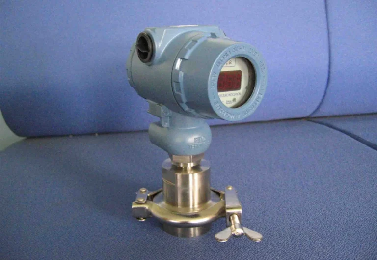
Oil-filled capacitive carries a different risk. The wetted diaphragm is still 316L, but silicone oil sits behind it. A rupture in abrasive service leaks oil into the process, which disqualifies the cell from food, pharma, and any batch operation where contamination triggers a discard. In those applications dry ceramic is the only correct answer.
Ceramic capacitive covers the widest media envelope but caps at 5 MPa. Sapphire piezoresistive covers the widest pressure range at higher cost.
Dimension 4 — Temperature Drift and Long-Term Stability
Silicon’s resistance changes with temperature roughly 20 times faster than it changes with strain. Temperature is therefore the hardest thing to engineer out of a piezoresistive cell. A raw bridge drifts ~2%/100 °C uncompensated, which is why every commercial piezoresistive transmitter carries a polynomial-compensation ASIC. Residual drift after compensation is what reaches your loop.
Ceramic capacitive cells drift slower at the cell, about 0.01–0.02% FS/°C, because the ceramic dielectric is thermally more stable than doped silicon and the reading is a ratio rather than an absolute bridge voltage. Oil-filled capacitive sits near 0.02% FS/°C: the oil expands, the reference cavity shifts, zero walks. Oil-filled takes longer to settle after a step but holds calibration longer once settled. See the MEMS pressure sensor review in MDPI Sensors for the thermal-mechanical model behind these numbers.
| Unit | Technology | Span shift 25 → 85 °C | 1-yr drift after cycling |
|---|---|---|---|
| HM20 | MEMS piezoresistive | +0.18% FS | +0.05%/yr |
| HM22 | High-accuracy piezoresistive | +0.12% FS | +0.04%/yr |
| HM50 | Piezoresistive + anti-corrosive | +0.09% FS | +0.03%/yr |
| HE26 | Ceramic capacitive | +0.06% FS | +0.02%/yr |
| HM12 | Ceramic capacitive OEM | +0.04% FS | +0.015%/yr |
| HM1151 | Oil-filled capacitive DP | +0.08% FS | +0.025%/yr |
Above 85 °C sustained, or outdoor installs cycling through a 50 °C seasonal swing, ceramic capacitive pulls ahead on span shift and long-term drift. Inside a narrow band (25 ± 10 °C year-round), a compensated MEMS cell is fine for a decade. Above ~150 °C process temperature, remote seals and capillaries take over; the high-temperature transducer guide covers that territory.
Case Snapshot — 120 Days on a Cement Slurry Line
Source: HMK field-service return data, 2024 cement-industry deployment. Customer identity withheld per supply agreement.
A cement producer running a raw-mix slurry line, pH 10.5–12.5 and 35% solids by mass, ran this comparison on two parallel DP loops measuring slurry-tank level. Identical process connections, identical 4–20 mA wiring, identical HART configuration. Only the sensing cell differed.
Loop A: diffused-silicon piezoresistive with 316L diaphragm, 0–600 kPa, installed upstream of a positive-displacement pump that generated pressure transients of 4.2× FS during priming. Loop B: ceramic capacitive HE26, same range, 99.6% Al₂O₃ diaphragm contacting slurry directly, no remote seal, no oil fill.
Results after 120 days:
| Metric | Loop A (piezoresistive 316L) | Loop B (ceramic capacitive) |
|---|---|---|
| Zero drift day 30 | +0.4% FS | +0.05% FS |
| Zero drift day 90 | +1.7% FS | +0.08% FS |
| Diaphragm pitting at day 90 | Yes, visible on disassembly | None |
| Overpressure transients > 4× FS | 62 (replaced at day 90) | 218 (still in service) |
| Replacements in 120 days | 1 unit + 2 re-zeros | 0 units, 1 re-zero |
The 316L diaphragm was being attacked by chloride in the slurry before the transients broke it, and each transient pushed the silicon closer to the creep regime driving the 1.7% FS zero drift. The ceramic cell sat outside both failure modes.
One case does not prove a technology. Hundreds of returns across chemical, cement, and pulp service point the same direction: corrosion plus overpressure cycling on the same process sheet leaves ceramic capacitive as the technology that clears the duty cycle silicon cannot.
Which Sensor to Spec — A Decision Framework
Datasheet accuracy does not tell you which unit is cheapest to own. Cost of ownership has three levers you can score without pulling a quote: how often the cell needs replacing in your duty cycle, how long it holds its trim, and how bad a failure gets.
Replacement frequency. Piezoresistive MEMS in clean compressed air runs five years. The same cell in slurry runs six months. Ceramic capacitive in that same slurry runs three years or more. The ratio drives annualised cost.
Calibration interval. How long the cell holds trim between re-zeros. Multiply re-zero labour by events per year using the Dimension 1 drift numbers.
Blast radius of failure. A 0.5% FS zero drift on a tank-level loop wastes product. A ruptured silicone-oil diaphragm in a pharmaceutical batch triggers a batch discard. Failure-cost magnitude multiplies the other two.
Decision rule, four quadrants:
- Clean media, narrow temperature, budget > 0.15% FS → piezoresistive MEMS. Default to HM20 class.
- Corrosive media, range < 5 MPa → dry ceramic capacitive, HE26 or HM12.
- Budget < 0.1% FS, static range < 10 MPa, oil acceptable → oil-filled capacitive, HM1151 DP class.
- Static pressure > 50 MPa → sapphire piezoresistive, HE28.
When NOT to pick piezoresistive silicon
Food and pharma where a diaphragm rupture cannot be recovered. Slurry with chloride above 500 ppm combined with transients > 4× FS.
When NOT to pick ceramic capacitive
Process pressure above 5 MPa. Accuracy budget tighter than 0.075% FS.
Straddle two quadrants? Specify the more conservative cell and recover margin on calibration interval.
Frequently Asked Questions
Match the cell to your process, not to the brochure.
Send us your process sheet — worst-case transient, wetted material, accuracy budget, temperature range — and we’ll match it to the right HMK unit from the piezoresistive or capacitive family.