How to Select the Right Industrial Temperature Sensor: A Two-Stage Decision Framework
You’re replacing a failed thermocouple, scoping a new line, or auditing a process loop—and the catalog has 40 variants. Most “selection guides” hand you a flat list of factors (range, accuracy, response time, vibration, cost, output) and leave you to assemble the answer yourself. That is how 90% of selection mistakes happen.
For the RTD-versus-thermistor choice in particular, see RTD vs thermistor.
Treat selection as two sequential decisions:
- Define operating temperature range (continuous + peak)
- Define required accuracy class
- Pick the sensing element (TC type, RTD class, thermistor, or IR)
- Pick the assembly (sheathed, assembled, thermowell, explosion-proof) and the junction type (grounded, ungrounded, or exposed)
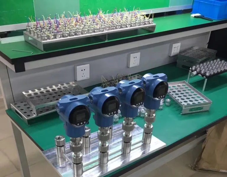
- Decide head-mount vs integral transmitter
Steps 1–3 are Stage 1: you choose what senses the temperature. Steps 4–5 are Stage 2: you choose how it survives and connects. Mixing them is what causes the wrong sensor to be specified.
Why Most “Selection Guides” Lead You to the Wrong Sensor
Search results for this query list the same six or seven factors and present them as parallel choices. They are not parallel. Sensing element decides the physics of measurement—what range you can read, what accuracy you can resolve, how fast the signal responds. Assembly decides whether the sensor survives in the actual environment and how its signal reaches the controller.
A flat list lets you specify a Type K thermocouple correctly for a 900°C furnace, then realize at install that the head you chose cannot fit the existing thermowell, the cable run drops accuracy by the time it reaches the PLC, and the area is classified Zone 1 so the assembly is non-compliant. The element was right. The assembly killed the project.
Stage 1 first, Stage 2 second—every time. The framework below walks each stage with concrete decision rules, then closes with a matrix you can apply to your own application.
Stage 1 — Choose the Sensing Element by Temperature Range and Accuracy
Stage 1 has one job: pick the element type that can actually read your temperature within your accuracy budget. Three rules, in order.
Rule 1: Temperature range is binary. If the element’s continuous operating limit does not cover your peak process temperature with margin, it is out. No further evaluation. A Type T thermocouple cannot measure 500°C, regardless of its accuracy advantage at low temp.
Rule 2: Accuracy class must match your process tolerance. A pharma reactor controlled to ±0.5°C cannot use a Class B PT100 (±0.30°C at 0°C, drifting wider with temperature). A general HVAC loop does not need a Class A. Match the class to what the loop actually controls.
Rule 3: Cost is a tiebreaker, not a driver. Once Rules 1 and 2 are satisfied, pick the cheaper option. Thermocouples are usually cheapest above 400°C. RTDs win below 400°C when accuracy matters. Thermistors win in narrow HVAC ranges.
Element Comparison
| Element | Temp Range | Typical Accuracy | Best For | Avoid When |
|---|---|---|---|---|
| Thermocouple Type K | -200 to +1260°C | ±2.2°C or 0.75% | Furnaces, kilns, exhaust, fast response | High accuracy below 200°C |
| Thermocouple Type J | -40 to +750°C | ±2.2°C or 0.75% | Reducing atmospheres, older retrofits | Oxidizing service above 540°C |
| Thermocouple Type T | -200 to +350°C | ±1.0°C or 0.75% | Cryogenic, food/pharma low-temp | Above 350°C |
| Thermocouple Type S/R | 0 to +1600°C | ±1.5°C or 0.25% | Glass, ceramic, steel furnaces | Routine process below 600°C (overkill cost) |
| RTD PT100 Class A | -200 to +600°C | ±0.15°C @ 0°C | Lab, pharma, custody transfer | Severe vibration, fast transients above 600°C |
| RTD PT100 Class B | -50 to +500°C | ±0.30°C @ 0°C | General process, HVAC primary loops | Tight-tolerance batch processes |
| Thermistor (NTC) | -50 to +250°C | ±0.1 to ±0.5°C | HVAC, narrow-range monitoring | Wide industrial range, harsh ambient |
| Infrared (non-contact) | -50 to +3000°C | ±1% reading | Moving targets, hostile or rotating surfaces | Reflective / low-emissivity surfaces |
Applying the Three Rules
A reactor jacket runs 80–140°C continuous with ±0.3°C process tolerance. Type K passes Rule 1, fails Rule 2. Class A PT100 passes both. Stage 1 result: PT100 Class A. Browse assembled thermal resistance assemblies or sheathed RTDs for this profile.
A cement kiln burner runs 1,100–1,250°C. RTDs are out (over range). Type K is borderline at peak; Type S handles it with margin and the long-term drift is lower at high temp. Stage 1 result: Type S thermocouple. Most jobs use assembled thermocouples here with a ceramic protection tube (handled in Stage 2).
A boiler exhaust gas line, 350–500°C, ±2°C tolerance, vibration present. Type K passes everything and is the cheapest. Stage 1 result: Type K thermocouple. Vibration drives the assembly choice in Stage 2.
Stage 1 is closed. Move to assembly.
Stage 2 — Choose the Assembly Configuration by Environment and Installation
A Type K element can be packaged five different ways. Pick the wrong package and the right element fails in three months. Stage 2 evaluates four dimensions.
Dimension 1: Process Medium Contact
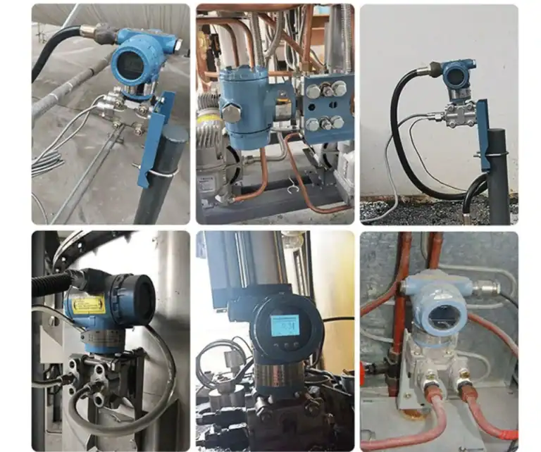
Direct insertion gives the fastest response and is cheapest. It is also non-removable without shutting down the line. If the medium is corrosive, abrasive, high-pressure, or you need on-line replacement, specify a thermowell and an assembled sensor that fits inside it, sized with our thermowell insertion length guide. The well takes the wear; the sensor pulls out for calibration or replacement without breaking the process.
Dimension 2: Atmospheric Hazard
Hazardous-area classification (IECEx, ATEX, NEC Class/Division) is non-negotiable. A Zone 1, Group IIC, T6 environment requires an explosion-proof housing rated for that exact classification. There is no workaround. For these applications, specify explosion-proof thermocouples or explosion-proof thermal resistance.
Dimension 3: Mechanical Stress
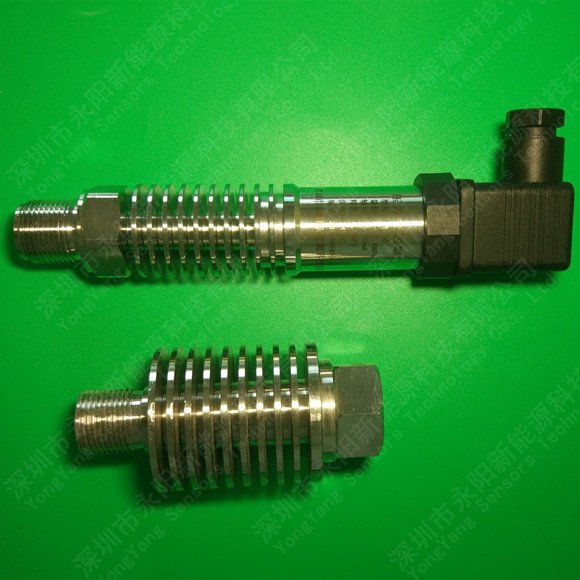
Vibration and impact destroy assembled sensors with ceramic insulators. Sheathed (mineral-insulated) construction—element embedded in compacted MgO inside a stainless tube—handles vibration, bending, and tight installations. Use sheathed thermocouples for engine exhaust, rotating equipment housings, OEM applications, and any installation where the sensor must bend to reach the measurement point.
Dimension 4: Signal Output and Cable Distance
A raw thermocouple sends millivolts. RTDs send resistance. Both signals degrade over distance and pick up EMI from VFDs, motors, and switching gear. Three options:
- Short runs (under 15 m), low-noise environment: send the raw signal to a controller-mounted input card.
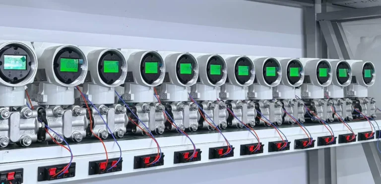
- Long runs or noisy plant: specify a head-mount transmitter that converts the signal to 4-20 mA or HART at the sensor head. The HM100 temperature transmitter handles this for both TC and RTD inputs.
- Long cable plus remote display required: use a rail-mount transmitter like the SBW temperature transmitter, or for hazardous areas the explosion-proof TC/RTD with integral transmitter.
Assembly Decision Table
| Environment Trait | Recommended Assembly |
|---|---|
| Corrosive media, online replacement needed | Assembled element + thermowell |
| Vibration, impact, tight bend radius | Sheathed (MI cable) |
| Hazardous area Zone 1 / Class I Div 1 | Explosion-proof TC or RTD |
| Cable run over 15 m, EMI environment | Integral head-mount transmitter (4-20 mA / HART) |
| OEM or space-constrained, no head | Sheathed without terminal head |
| High-temp furnace (>1400°C), corrosive atmosphere | Assembled S-type + ceramic protection tube |
The Quick-Reference Decision Matrix
Combine both stages against the application:
| Application Scenario | Stage 1: Element | Stage 2: Assembly |
|---|---|---|
| Boiler flue gas, 500°C, vibration | Type K thermocouple | Sheathed, MI cable, head-mount |
| Pharma reactor jacket, 140°C, ±0.3°C | PT100 Class A | Assembled + sanitary thermowell |
| Hazardous-area storage tank, ambient–80°C | PT100 Class B | Explosion-proof + integral 4-20 mA TX |
| Food process, -20 to +120°C, sanitary | PT100 Class A or Type T | Sanitary sheathed, tri-clamp fitting |
| Steel reheat furnace, 1,200°C+ | Type S thermocouple | Assembled + ceramic protection tube |
| Plastic injection nozzle, 280°C, fast response | Type J or K, sheathed Ø3 mm | Sheathed without head, OEM cable |
Match your application to the closest row, then verify against the four dimensions in Stage 2. The full configuration catalog is on the temperature sensors and transmitters category page.
Three Selection Mistakes That Cost You a Re-Order
Mistake 1: Substituting Class B PT100 for Class A without recalibrating the loop. Procurement swaps for cost savings; the control loop now reads with twice the sensor uncertainty. Batch quality drifts out of spec before anyone correlates the cause. Either keep the original class or formally re-validate the loop tolerance.
Mistake 2: Direct-inserting an assembled sensor into a corrosive medium without a thermowell. The stainless sheath develops pitting within weeks. Within six months it perforates and the sensor wets through. Replacement requires shutting the process. The thermowell adds 10–15% to the part cost and removes the shutdown.
Mistake 3: Running raw thermocouple millivolts over 30 meters of cable past variable-frequency drives. Readings drift, fluctuate with VFD load, and never match the handheld check. The fix is a head-mount transmitter at the sensor that converts to 4-20 mA before noise hits the cable. Specify it at design, not after commissioning.
All three mistakes share one root cause: skipping Stage 2 after finishing Stage 1. The element was correctly chosen and the assembly was treated as an afterthought.
Once you have narrowed the element down to an RTD, see Pt100 vs Pt1000 to settle the element value before you write the spec.
FAQ — Industrial Temperature Sensor Selection
Next Step: Match Your Application to a Specific Configuration
Two ways to act on this framework today:
- Browse configurations by sensor type and rating on the temperature sensors and transmitters page. Each product page lists supported temperature range, accuracy class, and assembly options.
- Send the application brief—process medium, continuous and peak temperature, accuracy requirement, hazardous-area class, cable length, output signal needed—to engineering and receive a model recommendation within one business day at Contact Us.
Once you have narrowed the choice down to the two platinum-based options, our side-by-side RTD and thermocouple comparison walks through accuracy classes, drift mechanisms, wiring configurations, and the 500°C rule that working engineers use to pick between them.
See also: the ASME PTC 19.3 TW-2016 wake frequency calculation walk-through — the bench-to-publication six-step workflow.
About the Author — Ye Dong (叶东), Temperature Product Engineer
With over 40 years of industrial instrumentation experience, Ye Dong holds the rank of Professor-Level Senior Engineer (教授级高级工程师). Before leading HMK-TECH’s temperature product line, he served as Deputy Chief Engineer at both the Beijing Design Institute of China Petrochemical Group (Sinopec) and Sinopec Engineering Construction Co., Ltd., where he designed instrumentation and automation systems for major refinery and chemical plant projects. His expertise spans thermocouples, RTDs, and transmitter technologies. Fushun Petroleum Institute, Department of Automation, 1982. View Ye Dong’s full profile → Send your application brief for a sensor recommendation.
Related reading: pick the right transmitter form factor: head mount vs DIN rail — a seven-criterion decision guide for picking head mount or DIN rail temperature transmitters.