RTD Wiring: 2-Wire, 3-Wire & 4-Wire Explained (2026)
An RTD is an extremely stable sensor. A calibrated Class A Pt100 will drift less than ±0.1 °C in a full year of service in a clean process. The accuracy class behind that figure is set out in Pt100 Class A vs Class B. And yet, field technicians routinely find the same RTD reporting 2, 3, even 5 °C off what an NIST thermometer says an inch away.
Ninety-nine times out of a hundred, the sensor is fine. It is the wiring between the sensor and the transmitter that is wrong. That gap between theoretical sensor accuracy and delivered accuracy is decided by one choice: 2-wire, 3-wire, or 4-wire configuration. Get it wrong and no amount of recalibration saves you, because lead-wire resistance is being added to the element resistance and being interpreted as temperature.
This guide walks through every configuration engineers and technicians actually use in the field, with the math, the color codes, the installation diagrams, and — uniquely — the diagnostic methods used on the floor when a reading looks suspect. By the end you will be able to pick the right topology, wire it correctly to a transmitter or a PLC analog input, and prove it is working before you hand it off to commissioning.
The Lead-Resistance Problem in a Nutshell
An RTD measures temperature by measuring resistance. A Pt100 reads exactly 100.00 Ω at 0 °C and rises about 0.385 Ω per °C. That means every 0.385 Ω of parasitic resistance anywhere in the measurement loop registers as 1 °C of temperature error.
Copper wire is not free resistance. Standard 22 AWG copper has a resistance of roughly 0.053 Ω per meter per conductor at room temperature. A modest 30-meter cable run back to the control room with two conductors in series therefore contributes about 3.2 Ω of lead resistance. In a 2-wire circuit, that is roughly 8 °C of error added to whatever the sensor is reporting.
Worse, the resistance of copper drifts with its own temperature, roughly 0.4 % per °C. A cable running through a hot cable tray in summer reads higher than the same cable in winter, so your “fixed” offset is itself temperature-dependent. That is what 3-wire and 4-wire configurations were invented to solve.
2-Wire RTD Wiring — The Simple One
A 2-wire RTD has exactly two leads — one color at each end of the platinum element. The element resistance, plus both lead wires, appears as a single series value to the transmitter. There is no way to mathematically separate the lead contribution from the element contribution.
When It’s Acceptable
2-wire is fine for short-distance, non-critical applications: a thermostat in an HVAC duct three meters from its controller, a local panel indicator, a protective thermal cut-out, or a spare port in a multi-sensor assembly. Many transmitters accept a 2-wire input and let the user punch in a fixed “lead compensation” ohm value during commissioning, which works provided the ambient along the cable stays stable.
Typical Error Math
Rule of thumb: figure on a 1 Ω per 100 feet round-trip penalty for 22 AWG copper, or roughly 0.033 Ω per meter round-trip. Translate that into °C by dividing by 0.385:
| Cable run (round-trip) | Lead Ω (22 AWG) | Error added (°C) |
|---|---|---|
| 3 m (10 ft) | 0.1 Ω | 0.26 °C |
| 30 m (100 ft) | 1.0 Ω | 2.6 °C |
| 100 m (330 ft) | 3.3 Ω | 8.6 °C |
| 300 m (1000 ft) | 10 Ω | 26 °C |
You can see why 2-wire breaks down fast outside of very short runs. Anything longer than about 10 meters or anywhere accuracy matters: skip it.
3-Wire RTD Wiring — The Industrial Workhorse
A 3-wire RTD bonds two conductors to one end of the platinum element and one conductor to the other end, for a total of three leads. This is by far the most common configuration in oil and gas, power, pharma, food processing, and general plant instrumentation.
How the Wheatstone Bridge Cancels Lead Resistance
The transmitter places the Pt100 element into a Wheatstone bridge such that two of its three leads are on opposite arms of the bridge. Current flows down one lead and back up another, so both leads carry the excitation — but because they occupy equal-but-opposite bridge arms, the circuit mathematically subtracts one from the other. The third lead acts as a voltage-sense line and carries essentially zero current, so its own resistance has no effect on the reading.
Effectively, the bridge subtracts the resistance of one lead from the resistance of another identical lead, and the remainder is just the Pt100 element. The element reading is clean.
The Three-Rule Requirement — What Most Guides Miss
The bridge math only works if the two compensating leads are identical. Three rules, all three must hold:
- Same material. Do not splice tinned copper to plain copper in the middle of a run. Do not extend a 3-wire RTD cable with a pair of spare conductors from a different cable.
- Same gauge (AWG). A 22 AWG lead and a 20 AWG lead have different per-meter resistance. The bridge will still subtract, but it will subtract the wrong amount.
- Same length. Every conductor in the cable must run the full distance from sensor to transmitter. Cutting one lead short “because it reaches the terminal already” defeats cancellation.
Most 3-wire RTDs in field service that still show unexplained offset have a violation of one of these three. This is the number-one cause of bad 3-wire readings on the floor, and it is almost never called out in a generic wiring guide.
Practical accuracy delivered by a properly-executed 3-wire Pt100 loop: around ±0.3 to ±0.5 °C total on 100 m of 18–22 AWG cable — good enough for more than 90 % of industrial work.
4-Wire RTD Wiring — True Kelvin Accuracy
A 4-wire RTD uses two conductors at each end of the platinum element. The transmitter pushes excitation current down two of them (the “force” pair) and measures the voltage across the element using the other two (the “sense” pair). Because the sense leads carry near-zero current, their resistance contributes near-zero error — lead resistance simply drops out of the measurement, period.
This is what laboratories mean by a Kelvin (or four-terminal) measurement.
Why Lab and Pharma Insist on It
In validated GMP pharmaceutical lines, SIP/CIP loops, reference calibration stations, and cryogenic research, ±0.1 °C matters. 3-wire’s residual mismatch error — even on well-matched cable — tends to live in the 0.1–0.3 °C band. 4-wire removes the wiring loop from the error budget entirely, leaving only the element itself and the transmitter’s own A/D accuracy.
On very long runs (100 m+) 4-wire also beats 3-wire outright, because even tiny mismatches in cable resistance scale linearly with distance and 4-wire doesn’t care about matched mismatch.
Cost and Complexity Trade-off
The downsides: a 4-conductor cable costs more than 3, terminal blocks take more space, and not every transmitter or PLC analog-input card accepts a 4-wire input (many industrial cards are 3-wire only). If your transmitter is 3-wire and you have 4 leads at the sensor head, you simply jumper one of the extra conductors at the head and run 3-wire — no harm done, no benefit either.
Configuration Decision Matrix
Use this table as a first pass when choosing a topology.
| Criterion | 2-wire | 3-wire | 4-wire |
|---|---|---|---|
| Delivered accuracy (100 m cable) | ±3 to ±10 °C | ±0.3 to ±0.5 °C | ±0.05 to ±0.15 °C |
| Max recommended cable run | ~10 m | ~300 m | 1,000 m+ |
| Cable cost (per meter) | Lowest | Mid | Highest |
| Transmitter compatibility | Universal | Universal | Check spec |
| Requires matched leads | N/A | Yes (critical) | No |
| Suitable for GMP / metrology | No | Rarely | Yes |
| Typical use | Local thermostats, cut-outs | General industrial | Labs, calibration, pharma |
If you have to pick one as a default for a new plant design: 3-wire Pt100. It is the configuration the overwhelming majority of HMK customers, and the global process industry, specifies — good accuracy, universal transmitter support, reasonable cable cost.
Pt100 Color Codes — IEC 60751 and Common Variants
Color coding on RTD leads is not fully standardized. IEC 60751 defines a reference convention, but manufacturers (and especially US-built sensors) deviate. If the head has a wiring diagram printed on the inside of the lid, trust that over any generic table. Here are the most common codes you will see on field equipment.
| Configuration | IEC 60751 (international) | Common US / manufacturer variant |
|---|---|---|
| 2-wire | 1 × red + 1 × white | 1 × red + 1 × white |
| 3-wire | 2 × red (shorted) + 1 × white | 2 × red + 1 × white, or 2 × white + 1 × red |
| 4-wire | 2 × red + 2 × white | 2 × red + 2 × white |
Interpretation rule: the two same-color leads are always the two leads bonded to the same end of the platinum element. If you see two red leads, they are shorted together inside the sensor head. If you see two white leads, same thing, on the other end.
When in doubt with an unmarked sensor, use an ohmmeter at room temperature: any two leads that read near 0 Ω are leads bonded to the same end of the element. Any two leads that read near 110 Ω are across the element.
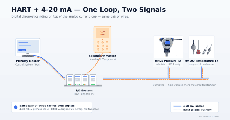
Wiring Pt100 to a 4–20 mA Transmitter, PLC, or DCS
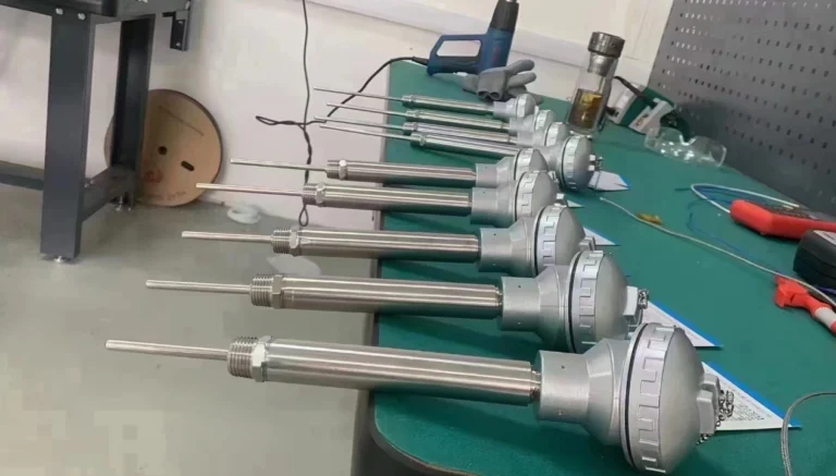
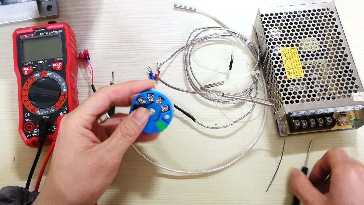
Real systems almost never wire an RTD directly into a PLC analog-input card over long distance. The better practice is to mount a head-mount transmitter — a small circular board that fits into the connection head of the sensor — which converts the resistance into a 4–20 mA loop signal. Then only 2 wires leave the sensor head and travel to the PLC. This gives you long cable immunity, simpler PLC wiring, and typically better accuracy than feeding raw RTD resistance all the way home.
Head-Mount Transmitter Hook-up (HMK WZP with SBW-type transmitter)
At the sensor head, the RTD’s 3 internal leads terminate on the transmitter’s RTD input terminals (commonly labeled 1–2–3, or A–B–B′). The two terminals that share the same physical end of the element receive the two same-color wires; the third wire goes to the unmatched terminal. On the transmitter’s output side, two terminals labeled + and − carry the 4–20 mA signal back to the PLC through a pair of ordinary copper conductors, loop-powered from a 24 V DC supply.
Terminal map, at the head:
[RTD 3-wire]  ─►  [Transmitter RTD in: 1, 2, 3]
                            │
                   [Transmitter 4-20 mA out: +, -]
                            │
                   2-conductor cable
                            │
[PLC AI card +]  ◄──  +  ──┘
[PLC AI card -]  ◄──  -
[24 VDC supply] provides loop power
Direct RTD-to-PLC Wiring (no transmitter)
If you are feeding a PLC AI card directly (supported by Siemens ET 200, Allen-Bradley 1769-IF4I RTD, and most DCS marshalled cabinets), match the card’s declared configuration: if the card says “3-wire RTD”, give it 3 wires with the two shorted leads on the two adjacent terminals and the third on the isolated one. The card itself performs the bridge cancellation.
Common wiring mistake: looping the 3-wire RTD into a 4-wire card without jumpers. A 4-wire AI card is looking for two force + two sense leads and will float one of them if only three are connected, producing a noisy drift. Either match the RTD config to the card, or add a jumper wire between the two “force” terminals at the card end to create a forced 3-wire equivalent. Always check the card manual.
Shielding and Grounding
- Use twisted, shielded instrumentation cable (often called “PVC/OS/PVC” or “TC-ER” in the US).
- Tie the shield to earth at one end only — typically the panel end, never both ends (which creates a ground loop and couples 50/60 Hz noise directly into the reading).
- Keep RTD cables at least 300 mm away from VFD power cables and motor runs. A shielded cable is not magic against power-frequency coupling from a nearby 480 V feeder.
For the 4–20 mA loop side, see the companion guide on 4–20 mA transmitter wiring — same loop physics applies.
Field Diagnostic Methods — How to Check a Suspect RTD Run
This is where most generic wiring guides stop. Here are the three techniques that instrumentation engineers use on the floor, rewritten as a proper field protocol you can hand to a technician.
The Short-Circuit Method
Use it when: You suspect a broken lead or an intermittent connection somewhere in a 3-wire run.
- Disconnect the RTD at the head.
- At the far end (the PLC or transmitter input), short the two same-color (e.g. white-white) terminals together with a jumper.
- At the head end, put an ohmmeter across the two wires that are now jumpered together through the cable.
- A healthy cable reads roughly twice the one-way wire resistance (for 22 AWG, that’s about 0.1 Ω per meter total — so 3 Ω for a 30-meter run).
- Open circuit → one leg is broken. Very high resistance (> 10 Ω on a short run) → bad termination or corroded connector. A zero reading → the jumper is shorting out your measurement, reapply it properly.
The Swap Method
Use it when: Readings look plausible but seem biased — off by a consistent 1 or 2 °C, drifting when weather changes, or the same RTD reads differently after an instrument was moved.
- Note the current reading.
- At the transmitter end, swap the “A” lead with one of the “B” leads in their terminal positions.
- Return to the display.
- If the reading shifts by the same amount in the opposite direction, the three leads are not identical (different material, gauge, or length). One or more of the 3-wire rules is being violated.
- If the reading does not change, lead mismatch is not the problem — look at the element itself, the terminations, or the transmitter configuration.
The Two-Point Element Check
Use it when: You want to confirm the platinum element itself is good, independent of the cable.
- Disconnect at the head.
- Measure resistance directly across the element terminals in the sensor head (bypass the entire cable).
- At ambient room temperature (call it 25 °C), a healthy Pt100 reads about 109.7 Ω.
- Dip the sensor tip in a glass of ice water (0 °C reference) — it should read 100.0 Ω ± tolerance.
- Large deviations at either point → the element is damaged. Replace the sensor, not the cable.
These three checks, done in sequence, isolate the fault to the cable, the leads, or the element every time, with no special equipment beyond a digital multimeter.
RTD Standards Cheat-Sheet
Pt100 and Pt1000 elements are covered by multiple national and international standards. Most specifications are compatible at 0 °C (100 Ω reference), but diverge in temperature-coefficient and tolerance-class definitions. If you’re working across markets, this cross-reference is what you need.
| Standard | Region | Notes |
|---|---|---|
| IEC 60751 | International | The reference standard. α = 0.003851 °C−1. Classes AA, A, B, C defined. |
| ASTM E1137 | USA | Adopts IEC 60751 with equivalent tolerance classes (“Class A” and “Class B”). |
| JIS C1604 | Japan | Earlier versions used α = 0.003916, newer versions follow IEC 60751. |
| GB/T 30121-2013 | China | Industrial Pt RTDs. Aligned to IEC 60751 α. Class A and B identical formulas. |
| JB/T 8623-1997 | China | Older industrial assembly standard for Pt/Cu resistance thermometers. |
| DIN 43760 | Germany (legacy) | Historic European standard, superseded by IEC 60751 in practice. |
Tolerance Formulas (from GB/T 30121-2013, identical to IEC 60751)
- Class A: ± (0.15 + 0.002 × |t|) °C, valid −100 °C to +450 °C
- Class B: ± (0.30 + 0.005 × |t|) °C, valid −196 °C to +600 °C
- Class AA (tighter): ± (0.10 + 0.0017 × |t|) °C, valid 0 °C to +150 °C
- Class C (looser, industrial HVAC grade): ± (0.60 + 0.010 × |t|) °C
Worked example at 200 °C:
- Class A allowable error = ±(0.15 + 0.002 × 200) = ±0.55 °C
- Class B allowable error = ±(0.30 + 0.005 × 200) = ±1.30 °C
That is the full allowable budget from the sensor element alone, before wiring-loop error is added. A 2-wire run can easily consume this entire budget in cable resistance alone — another argument for 3-wire as the minimum sensible default.
Common Installation Mistakes That Still Pass Commissioning
These five errors get past the cold-loop check because they do not stop the signal from flowing. They show up later, during performance audits or QC deviations.
- Shield grounded at both ends. Creates a ground-loop current that gets capacitively coupled into the RTD reading. Classic symptom: a sinusoidal temperature oscillation at 50 or 60 Hz that averages out on a slow logger but biases fast-loop control.
- 3-wire cable extended with a 2-conductor splice. The third wire is “borrowed” from somewhere, breaking the equal-length rule. Appears in facility retrofits where cable trays are reused.
- Head-mount transmitter configured for 2-wire when the sensor is 3-wire. Terminal 3 is left floating. The reading will look roughly right but is taking lead resistance as a signed bias, and drifts with ambient cable temperature.
- Mixed wire gauges in the same run. 22 AWG from sensor head to a junction box, then 18 AWG from junction box to panel. Looks fine, violates the equal-gauge rule.
- RTD cable pulled through a VFD cable tray. Even with shielded, twisted cable, 480 V PWM switching will inject noise into a high-impedance Pt100 loop. Always run RTDs in a dedicated signal tray, or at minimum a separated segment of a shared tray with a grounded metal divider.
Frequently Asked Questions
A 2-wire RTD has one conductor at each end of the sensing element and no way to separate lead-wire resistance from the element, so it adds copper resistance directly to the reading. A 3-wire RTD duplicates one lead so a Wheatstone bridge in the transmitter can subtract the lead resistance out. A 4-wire RTD uses two conductors at each end to create a true Kelvin measurement that fully eliminates lead resistance.
Use 3-wire for general industrial plant work where ±0.3 to ±0.5 °C is acceptable — this covers roughly 90 % of process applications. Use 4-wire for laboratory, GMP pharmaceutical, metrology, or long-cable applications where ±0.1 °C or better is required and cable mismatch cannot be guaranteed.
The most common IEC 60751 convention for a 3-wire Pt100 is two red conductors (shorted to one end of the element) and one white conductor (to the other end). A 4-wire Pt100 uses two red plus two white. US-manufactured sensors often swap these colors. The rule that always applies: the two same-color leads are bonded to the same element terminal internally.
Yes, but not by plugging in only three wires. Jumper the two “force” terminals together at the card end so the card sees a pseudo-3-wire setup. Check the specific card’s manual — most modern cards, including Siemens 6ES7 analog input modules, explicitly document this option.
Measure resistance directly across the element at the sensor head, bypassing the cable. At 25 °C a healthy Pt100 reads about 109.7 Ω; at 0 °C (ice water), about 100.0 Ω (cross-check resistance values with our Pt100 resistance-to-temperature calculator). Significant deviation at either point means the element is damaged. If the element reads correctly but the system reading is wrong, the fault is in the wiring or transmitter.
2-wire: about 10 m before errors become meaningful. 3-wire: up to 300 m with matched cable. 4-wire: 1,000 m or more, limited mostly by transmitter drive capability rather than cable resistance. For runs over 30 m, use a head-mount 4–20 mA transmitter and run only the loop signal over the long cable — this eliminates cable length as an accuracy variable entirely.
No. It only eliminates lead-wire error if the three leads are identical in material, gauge, and length. Any mismatch leaves a residual error proportional to the mismatch. A well-executed 3-wire run on matched cable typically delivers 0.1–0.3 °C residual error from the wiring — better than 2-wire, not as good as 4-wire. For applications that cannot tolerate this residual, step up to 4-wire.
Conclusion
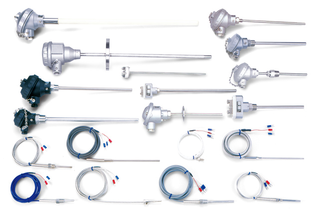
Three topologies, one Pt100 element, ten-fold differences in delivered accuracy. Pick by cable length and accuracy requirement, respect the equal-material / equal-gauge / equal-length rule on 3-wire, and use the short-circuit, swap, and two-point element checks when a reading looks suspect. HMK supplies Pt100 and Pt1000 RTDs from 2-wire thermostats through 4-wire laboratory-grade assemblies, plus matched head-mount 4–20 mA transmitters so the wiring topology stops being your accuracy bottleneck. If you’d like help specifying for a specific application, our engineering team is one email away — send us your application brief.
Lead-wire error is also the main reason to pick a Pt100 or a Pt1000 in the first place. Our Pt100 vs Pt1000 guide shows how the element value changes whether a two-wire run is even viable.