Submersible Level Transmitter: The 6 Failure Modes That Destroy Accuracy (and the Field Fixes)
A submersible level transmitter lists for $180 at one vendor and $1,800 at another. The datasheets almost match — both claim 0.25% FS accuracy, 4-20 mA output, 316 stainless. In a sewage pump well, the cheap one fails in six months. The better one is still running seven years later. Accuracy class explains none of that gap.
New to spec’ing one? Start with how to choose a well water level sensor.
What does the work is the hardware’s response to six specific environmental stresses: lightning transients, vent-tube condensation, silt, cable damage, freeze expansion, and chemical attack. Pick a probe that handles the dominant stress for your site and commissioning practice handles the rest. The diagnostic routine at the end is what our field team runs when a probe shows 22 mA at 3 a.m. and the plant supervisor wants an answer before the morning shift.
What a submersible level transmitter actually measures
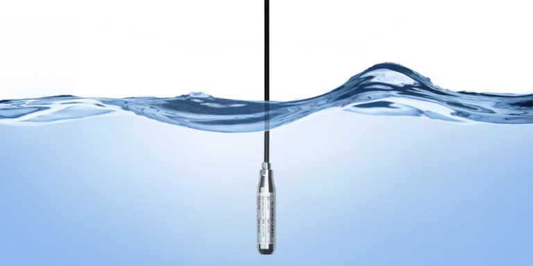
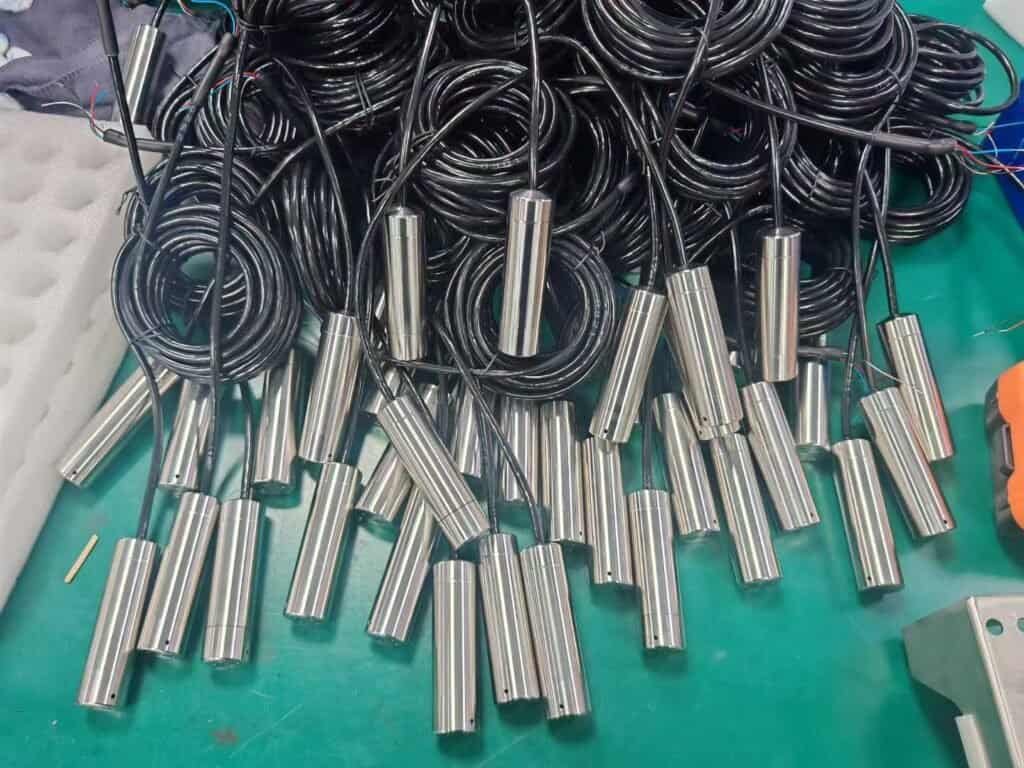
A submersible level transmitter is a pressure sensor packaged into a sealed probe that hangs in the liquid. It reads the hydrostatic head — the weight of the water column pressing on the diaphragm — and converts that reading into a 4-20 mA loop signal. P = ρgh does the rest of the math, so depth tracks output linearly.
For the underlying principle — and how it routes to either a submersible probe or a DP transmitter — see our hydrostatic level measurement guide.
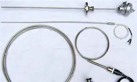
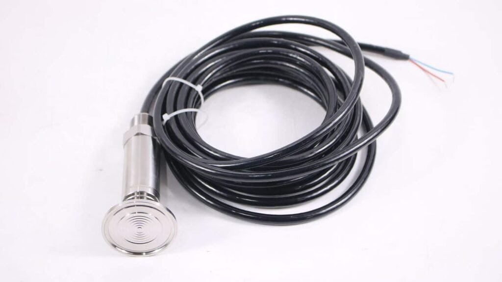
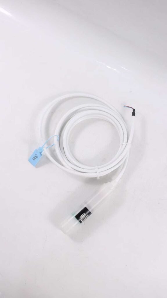
The immersion housing is typically IP68 with double or triple gland seals, a 316L or Hastelloy diaphragm, and a polyurethane- or FEP-jacketed cable. What makes the probe behave like a water-depth sensor rather than a barometer is the vent tube: a thin pneumatic line runs the full cable length up to a breather cap, so atmospheric pressure equalises against the back of the diaphragm. The vent is what lets the reading track depth instead of the weather, and it is also the component that gets abused most in real installations.
Submersible probes compete with ultrasonic, radar, and magnetostrictive instruments, each strong on different edge cases — vapour, foam, agitation, crystallising media. Use the hydrostatic pressure calculator to convert depth to head pressure in any units. To go the other way — translate a submersible probe’s pressure reading into liquid depth with full SG and unit control — see the pressure to liquid level calculator. From here on, assume a submersible probe is already the right topology and the question is which one survives your site.
Why datasheet accuracy does not predict field lifespan
Most Western buyer decks lean hard on the accuracy figure. A 0.1% FS probe sells as “twice as good” as a 0.25% FS probe, and the price tag follows. The math works on paper; in a sewage lift station it almost never matters.
Run the numbers on a typical 5 m range scaled to a 4-20 mA loop. A 0.25% FS error is 12.5 mm of water column, around 0.02 mA of loop current. Wave action on a working pump well moves the actual surface by 50 to 150 mm every time the pump cycles, and the PLC smoothing filter rolls over the sensor error along with the turbulence. The difference between 0.1% and 0.25% never reaches the operator’s screen.
Replacement frequency does. An eight-month drift from vent-tube condensation wrecks a control loop. A lightning strike that fries the input diode becomes a midnight call-out. A probe buried under 40 cm of silt forces an unplanned tank entry — confined-space permit, two technicians, a full shift of downtime — before anyone even asks whether the replacement sensor is 0.1% or 0.25% class.
You cannot average your way out of a dead probe. The rest of this guide is about the six field conditions that drive those binary failures.
The six failure modes — field frequency, not theory
Across several hundred installations in our service logs, the failure modes are nowhere near evenly distributed. Lightning, vent-tube condensation, and silt burial together account for about 70% of premature replacements across Chinese municipal and petrochemical service. The section below is ordered by that observed frequency rather than by how Western datasheets typically list the hazards.
1. Lightning surge damage
Every outdoor installation with a cable run of more than about 30 metres is an antenna. A nearby lightning strike induces a voltage transient that travels up the signal pair and the cable shield and appears at the probe terminals as several kilovolts for a few microseconds. The input circuit of a standard 4-20 mA transmitter is rated for 30 to 60 V. It does not survive.
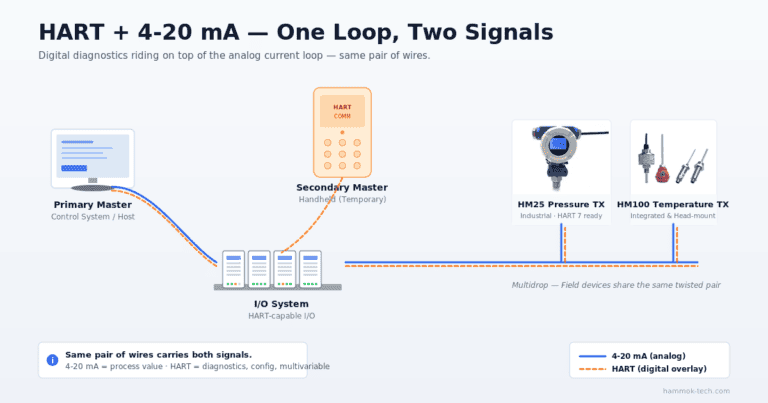
The Chinese national standard for surge immunity on industrial instruments is GB/T 17626.5-2019, aligned with IEC 61000-4-5. Installation class 3 requires 2 kV on signal lines, class 4 requires 4 kV. Most Western-branded submersible probes are tested to class 2 (1 kV) and quietly labelled “surge-protected”, which is not enough for a rooftop tank in a summer thunderstorm region. The HM21F surge-hardened variant uses a two-stage protection circuit — a gas discharge tube at the cable entry and a transient-voltage-suppression diode array on the signal board — tested to class 4 on the loop and class 3 on the vent-tube drain connection.
Field failure data from three municipal water utilities in southeastern China tracked over eighteen months: probes installed under shared lightning arrestors without a second-stage device at the probe itself had a 31% annual failure rate during the May–September storm season. Adding the internal suppression dropped that to 4%.
2. Vent-tube condensation
The vent tube is the second biggest killer, and almost nobody talks about it on English datasheets. The tube runs the whole cable length, so in any installation where the probe is cooler than the ambient air outside the tank — a chilled well, a buried sump, a night-cooled water tower — moist air enters the tube during the day, cools along the way, and condenses on the inside wall. Over weeks, water droplets accumulate in the tube. They partially block the atmospheric reference path and they load the diaphragm back with an uncertain water column of their own. The symptom is a slow 0.3 to 1.2 mA zero drift that field technicians mistake for sensor aging.
The fix is a desiccant cartridge at the breather end. Chinese municipal plants logging vent humidity continuously report that a silica-gel cartridge saturates in 3 to 6 months under normal outdoor service, and inside 6 to 8 weeks during monsoon season. Once saturated it stops working even though it looks unchanged, and a probe will drift against a saturated cartridge for months before anyone catches it. HM-series submersibles ship with a colour-change cartridge and a pre-glued replacement-log label on the junction box for that reason.
3. Silt burial and biological fouling
Sewage pump wells, stormwater sumps, and river intakes silt up. A probe resting on the bottom gets buried, and the diaphragm reads the compressed weight of the silt, not the water column. The fix is a stainless suspension cone or a side-mount bracket that keeps the probe 200 to 400 mm off the floor.
Biological fouling is the second-order problem. Municipal activated-sludge tanks build a fouling layer on any submerged surface within weeks. Once that layer bridges the diaphragm, the pressure transmission becomes nonlinear. A smooth-finish, low-surface-energy diaphragm — PTFE-coated on the HM21R variant — sheds that layer for two to three times longer than bare 316L. Quarterly cleaning with a low-pressure water jet restores accuracy without pulling the probe.
4. Cable damage
The cable is usually the weakest link. Three categories of damage show up repeatedly:
- Physical cuts from pump impellers, cleaning tools, or dropped equipment in manholes.
- Rodent attack where cables run through cable trays in outdoor pits.
- Hydrogen embrittlement of the outer sheath in wells with dissolved hydrogen sulfide.
An FEP-jacketed cable resists all three better than standard polyurethane, at roughly 1.8× the cost per metre. The decision depends on how much the installation will pay in unplanned entries per year — typically one avoided confined-space entry covers the price difference on the first replacement.
Long cable runs also introduce a different problem: voltage drop in the loop. At 24 VDC supply and 250 Ω loop load, a standard 0.5 mm² conductor pair carries usable signal to about 600 metres. Past that point, the loop voltage margin is tight enough that a 22 mA alarm-state current causes the transmitter to drop out. The voltage-drop table is in the installation section below.
5. Freeze expansion
Shallow wells, outdoor stormwater sumps, and groundwater monitoring bores in cold-climate service freeze from the top down. Ice expansion against the cable or the probe head crushes the vent tube closed — the reading goes flat — and can crack the diaphragm housing.
The practical defences are to drop the probe below the frost line (1.0 to 1.5 m below grade for most temperate-zone sites) or to specify a freeze-rated probe with a thicker stainless housing and a cable jacket rated for –40 °C. The HM21 stainless housing is 1.5 mm on the diaphragm cup against 0.8 mm on most budget imports, and it survives repeated freeze cycles in accelerated-aging tests on the bench.
6. Chemical attack
Media compatibility drives the diaphragm material choice.
- Clean water, neutral effluent, potable water: 316L diaphragm is fine, ten-year service life realistic.
- Brackish water, mild acidic wastewater, diesel fuel tanks: 316L corrodes within months. Hastelloy C-276 or a PTFE-coated 316L diaphragm (HM21R) extends life to five-plus years.
- Strong acid, strong chlorinated media: tantalum or ceramic diaphragm — outside the submersible probe envelope; move to an online chemical-seal differential-pressure transmitter instead.
The single most common selection mistake is specifying “316L, good for most applications” on a specification sheet when the application is an oilfield brine tank or a seawater desalination intake. The probe reads fine for three months, then the diaphragm pits through and floods the electronics. It is not repairable in the field.
Matching the dominant risk to the right HMK variant
Three field cases, drawn from our service reports in 2024–2025, show how the variant choice falls out of the failure mode ranking.
Case A — Sinopec Shengli oilfield brine tank. Produced-water tank, media: hot brine at 35–55 °C with 14,000 ppm chloride. Dominant risk: chemical attack on the diaphragm. Secondary risk: silt from formation solids. Lightning is low (tank is indoors inside a steel-roofed shed). Selected variant: HM21R — PTFE-coated 316L diaphragm, Hastelloy cable gland, side-mount bracket. Service life to date: 28 months with no drift, annual cleaning only.
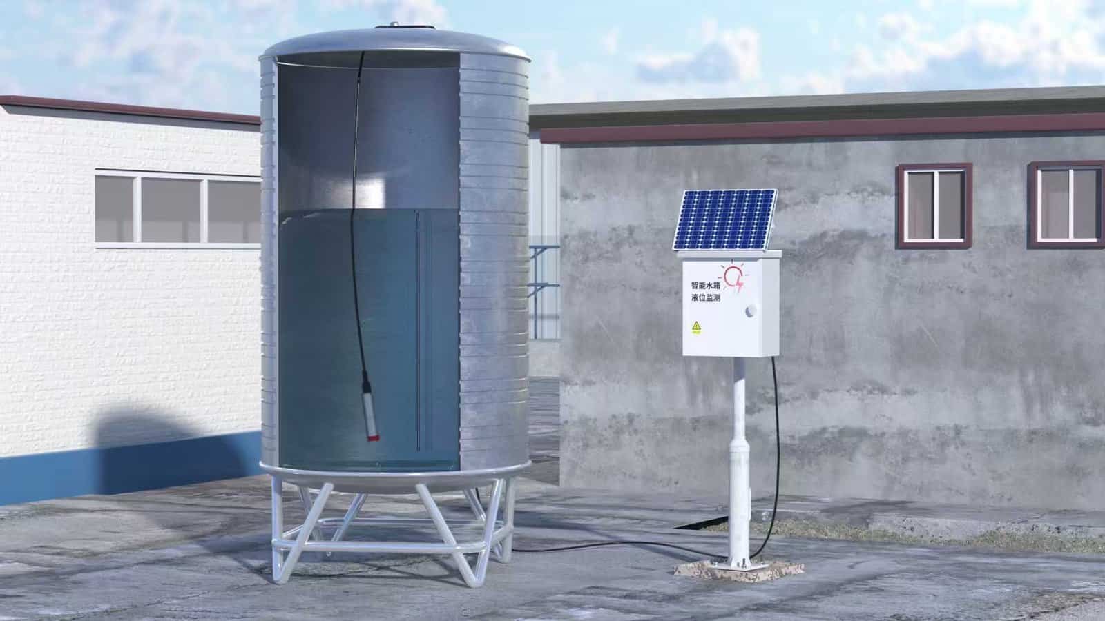
Case B — municipal wastewater plant lift station, southern Guangdong. Sewage in the wet well, media: domestic effluent with grease and surfactants. Dominant risk: lightning — the site sits on a hill with five prior probe losses in two summer seasons. Secondary risks: biological fouling and occasional freeze in January. Lightning dominates because failures are binary and the plant cannot afford repeated overnight call-outs. Selected variant: HM21F — GB/T 17626.5 class 4 surge protection, PTFE-smooth diaphragm for fouling resistance, standard polyurethane cable. Service life: 22 months with zero storm-season failures; prior probe lifetime was 5 months average.
Case C — groundwater monitoring borehole, grid of 40 wells in a North China Plain irrigation study. Remote wells 50 to 600 metres from any power source, measurement cadence one reading per hour. Dominant risk: none of the physical ones — the wells are quiet. The actual constraint is cabling and power. A wired 4-20 mA loop is uneconomic; the site needs wireless telemetry. Selected variant: HM210 — LoRa wireless submersible with integrated battery and an antenna that clears a 1 metre borehole casing. Three-year battery life at hourly logging. No cable, no lightning path, no vent-tube problem (the probe is sealed absolute, software-compensated for barometric pressure from the gateway station).
A short decision sequence covers most cases:
- Dominant risk is chemical → HM21R
- Dominant risk is lightning or electrical transients → HM21F
- Site is remote or the cable route is hostile → HM210
- Clean water, indoor, short cable run → HM21 base model
The rule of thumb: pick the variant for the dominant risk, then handle the secondary risks in the installation. The next section covers the installation side.
Installation decisions that determine lifespan
Four installation choices do more for service life than any upgrade to sensor accuracy.
Suspension, not bottom rest. Hang the probe from the cable, weighted if necessary with a stainless anchor 200 to 400 mm below the probe tip. Never let the diaphragm rest on the floor. In silty or biologically active media, suspend it 500 mm above the sediment line and clean the area around it quarterly.
Vent-tube routing and desiccant placement. The vent must rise continuously — no dips where condensate can pool — and terminate in a desiccant cartridge at a height above the maximum possible liquid level. Point the cartridge downward so gravity carries any loose condensate away from the breather hole. Replace the cartridge on a calendar cadence, not when it “looks used”: blue-to-pink silica gel changes colour at roughly 40% saturation, well before it is functionally useless.
Grounding and surge path. A submersible loop is grounded at one point only, at the receiving PLC or marshalling cabinet. Double-grounding creates a ground loop and invites lightning damage. If the site has a lightning-prone climate, add an intrinsically safe surge arrestor at the cabinet entry in addition to the probe’s own internal protection.
Zero offset at commissioning. Set the 4 mA point at the true empty-tank or lowest-possible-water condition, not at the installation-day water level. A zero set at a partial fill creates a permanent offset that gets blamed on the sensor months later.
Voltage-drop table for long cable runs (24 VDC, 250 Ω loop)
Cable pair 0.5 mm² Cu. Maximum usable cable length before the loop drops out of compliance during a 22 mA alarm-state reading:
| Loop supply | Loop load | Max one-way length |
|---|---|---|
| 24 VDC | 250 Ω | 620 m |
| 24 VDC | 500 Ω | 310 m |
| 28 VDC | 250 Ω | 950 m |
| 28 VDC | 500 Ω | 480 m |
At longer runs, either step up to 1.0 mm² cable, raise the supply voltage, or move to the HM210 wireless variant.
When readings drift — the 4-step field-tech diagnostic
Chinese field technicians use a four-step sequence that localises most submersible level faults in under ten minutes. It is taught informally in instrument-maintenance training and almost never appears in Western manuals.
Step 1 — visual and power check. De-energise the loop. Open the junction box. Look for water ingress, corroded screws, loose gland, insect nests. Re-energise and confirm the supply voltage at the probe terminals is within 18 to 30 VDC.
Step 2 — external insulation test. Use a 500 V megger between each signal conductor and the cable shield, and between conductors. Anything below 20 MΩ on a cable that has been in service more than a year indicates moisture ingress in the cable. The probe itself cannot be fixed; replace the cable assembly.
Step 3 — input short-circuit. Disconnect the probe signal pair at the cabinet and short the two conductors at the probe end of the cable. A healthy loop reads approximately 0 mA at the receiver (or the receiver goes to an under-range fault). If the reading is erratic, the fault is in the cable. If the reading is clean 0 mA, the fault is in the probe.
Step 4 — resistance swap. With the probe disconnected, measure resistance across its output terminals and compare to the datasheet value (HM21 series: 200 to 400 Ω typical). If the resistance is open or near zero, the input stage is damaged — usually a lightning survivor. Swap with a known-good probe from stock; if the fault follows the probe, you have confirmed the failure.
The sequence catches lightning damage, cable faults, and water ingress cleanly. It does not catch vent-tube condensation — for that, re-read the condensation subsection above.
When a submersible is the wrong choice
A submersible level transmitter is not the right answer for every liquid level problem. Four conditions push the decision toward a different technology.
Hot media above 85 °C. Saturated steam condensate lines, reactor cooling jackets, and high-temperature oil sumps will damage the probe seals and the cable jacket. Use a capillary-sealed chemical-seal differential-pressure transmitter instead.
Crystallising or high-viscosity media. Sugar syrups, molasses, certain polymer intermediates. The diaphragm fouls faster than any coating can resist. Use a radar level instrument that never contacts the media.
Heavy foam or floating solids. Aerated bioreactor tanks, sewage digesters with a scum layer. The probe reads the composite of liquid and foam as an unrealistic level. Use a guided-wave radar that sees through foam.
Very shallow ranges, under 300 mm. Hydrostatic sensitivity at that depth is below the noise floor of the diaphragm. Use an ultrasonic or a capacitive level switch instead.
For clean water tanks and other low-stress applications, the base HM21 submersible level transmitter still handles most of the load without the extra hardening.
Frequently asked questions
Pick the variant that matches your dominant risk
HM21F — Lightning-hardened
GB/T 17626.5 class 4 two-stage surge protection, 316L diaphragm, 0–100 m range. For outdoor pump wells, rooftop tanks, stormwater lift stations where lightning transients drive premature probe failure.
HM21R — Anti-corrosive
PTFE-coated diaphragm, Hastelloy gland, PTFE-jacketed cable. For saltwater, produced water, oilfield brine, and chemical effluent where 316L corrodes within months.
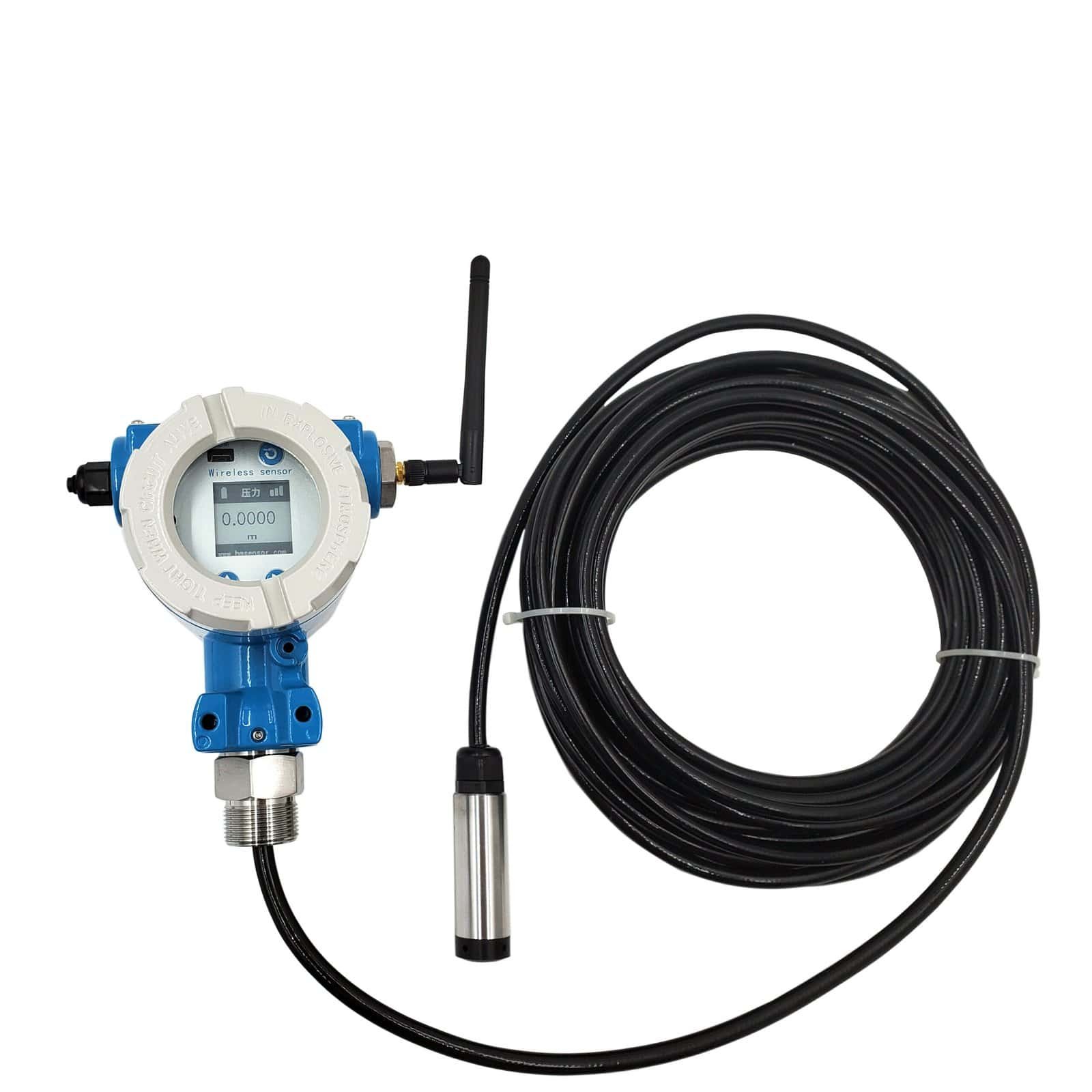
HM210 — LoRa wireless
LoRa wireless submersible with integrated battery and a 3-year log-cadence life. For remote monitoring wells, off-grid sumps, and groundwater study grids where cabling is uneconomic.