Cold Junction Compensation: How It Works & Where It Fails
If you’ve been reading thermocouple spec sheets or setting up a temperature transmitter, you’ve run into “cold junction compensation,” usually presented as a feature that’s either on or off, with no explanation of what it’s doing or how much accuracy it’s worth.
Cold junction compensation is not optional and it is not magic. It is a specific voltage correction, applied inside every modern temperature instrument, that converts a thermocouple’s raw output into a real tip temperature. Skip it, and a Type K thermocouple sitting in a 25 °C terminal block reads about 25 °C low. Get it wrong, and you’ll chase ghosts in your process loop that aren’t there. Cold junction is the reference end; the measuring end has its own grounded vs ungrounded junction decision that changes response time.
This article covers what CJC does, five ways it’s implemented, the error budget a modern built-in CJC gives you, and three field failure modes that bite engineers after a year or two in service. Run the math yourself on the Thermocouple Calculator.
What Cold Junction Compensation Does
Cold junction compensation (CJC) is the process of correcting a thermocouple’s measured voltage for the actual temperature at its cold (reference) junction, so the corrected voltage matches what the same thermocouple would produce if its cold junction were held at exactly 0 °C. The correction adds an offset voltage equal to the EMF that the thermocouple type would generate between 0 °C and the measured cold-junction temperature. Once that offset is applied, the corrected voltage can be looked up directly in the standard EMF table (IEC 60584-1:2013, GB/T 16839.1-2018) to return the tip temperature.
Why the correction is needed
A thermocouple is two wires of different metals joined at the tip. Heat the tip, and the Seebeck effect produces a small voltage across the open end. That voltage depends on the difference between the tip (hot junction) and the open end (cold or reference junction), not on the tip alone. A Type K thermocouple reading 400 °C against a 0 °C reference gives 16.397 mV. The same 400 °C tip, with its reference end sitting in a 25 °C terminal block, gives 15.394 mV. The tip didn’t change; only the reference did, and the standard EMF tables are anchored at 0 °C.
How the correction is implemented
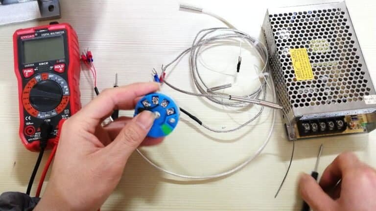
A small temperature sensor (RTD, thermistor, or IC sensor) is mounted next to the terminal block where the thermocouple wires attach. The instrument reads that sensor to get the cold-junction temperature, computes the EMF between 0 °C and that temperature using the thermocouple’s own polynomial, and adds it to the raw thermocouple voltage before the table lookup.
That calculation used to be done physically. Laboratories kept the reference junction in an ice-water Dewar flask, which holds 0 °C to ±0.001 °C as long as somebody tops up the ice. Fine for metrology, impractical in a refinery. Modern temperature transmitters do the same correction electronically and arrive at the same answer.
Five Ways to Compensate the Cold Junction
Engineers across different eras and industries have solved the same problem five different ways. Four are historical or niche. One is what’s in your transmitter right now.
| Method | Principle | Typical accuracy | Where you still see it |
|---|---|---|---|
| Ice bath | Physical reference junction in ice-water slurry at 0 °C | ±0.01 to ±0.05 °C | Metrology labs, calibration houses, thermocouple certification |
| Offset correction | Operator reads ambient, adds a fixed offset manually | ±1 to ±3 °C | Legacy panel meters, training rigs |
| Bridge compensation | Unbalanced Wheatstone bridge with a temp-sensitive resistor biases the TC signal | ±0.5 to ±1 °C | Older analog transmitters, some portable indicators |
| Copper-resistance | Copper coil at the terminal block shifts voltage proportional to ambient | ±0.5 °C | Sub-assemblies in older Chinese-built temperature controllers |
| IC auto-compensation | Silicon sensor (or precision thermistor) at terminals, MCU computes polynomial offset | ±0.2 to ±0.5 °C | Every modern transmitter, DCS input card, data logger |
The last row is what a Hammok HM100 or any other 4-20 mA smart temperature transmitter built since about 2005 does. The cold-junction sensor is inside the head, within a few millimeters of the terminals where the thermocouple extension wires land. Firmware stores the ITS-90 polynomial for each supported type (K, J, T, E, N, R, S, B), reads the cold junction every measurement cycle, and applies the correction before the 4-20 mA or HART output is generated. For high-temperature cyclic service above 500 °C, Type N thermocouple assemblies avoid the preferential-oxidation drift mode that affects Type K in that range.
Worth noting: the ice bath is still the standard of truth. When a calibration lab certifies a thermocouple to ±0.1 °C, they’re using an ice bath (or a dry block traceable to one) as the reference. Nothing a transmitter does is more accurate; it’s just more practical.
The Distinction That Costs Readings: Compensating Wire vs CJC
Engineers regularly conflate compensating wire and cold junction compensation often enough that it shows up as a common field error. They are not the same thing.
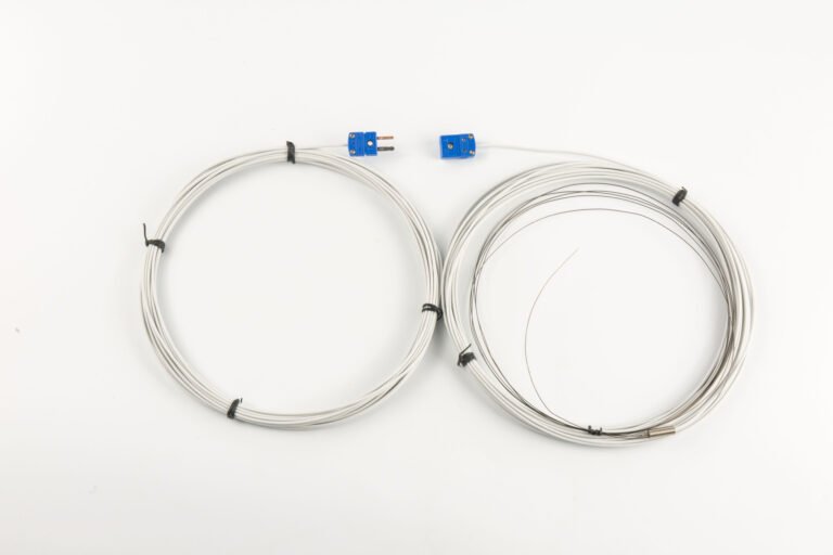
Compensating wire is a pair of extension wires with the same thermoelectric characteristics as the thermocouple, used to move the cold junction from wherever the thermocouple terminates to a more controlled location (usually the transmitter terminals inside a junction box). It does not compensate for anything. It only shifts the cold junction geographically.
Cold junction compensation is the electronic correction applied at that final cold junction, based on its actual temperature.
You need both. The compensating wire gets the reference junction to a place with a CJC sensor; the CJC sensor tells the instrument what that junction’s temperature is. Use plain copper wire between the thermocouple head and the transmitter and you’ve introduced an uncompensated thermoelectric boundary at every copper/alloy joint. I’ve seen 3-5 °C drift on a K-type loop traced back to exactly this.
CJC Error Budget: What It Actually Costs You
CJC is not free accuracy. Every method above introduces its own error, which stacks with the thermocouple’s basic tolerance, extension-wire matching, lead resistance, and ADC noise.
For a Type K thermocouple reading 400 °C through a modern transmitter with IC-based CJC, a realistic error budget looks like this:
| Source | Typical value | Notes |
|---|---|---|
| Thermocouple Class 2 tolerance (IEC 60584-1) | ±2.5 °C or ±0.75% of reading, whichever is greater | The wire itself. Class 1 is ±1.5 °C but costs more |
| CJC sensor accuracy (HM100 spec) | ±0.3 °C | From HMK HM100 datasheet at 25 °C ambient |
| CJC sensor drift over 10 °C ambient swing | ±0.1 °C | IC sensor tempco, well-controlled |
| ADC linearity + ref drift | ±0.15 °C | 24-bit resolution, across industrial temp range |
| Extension wire matching (if compensating cable used) | ±0.5 to ±1.0 °C | Depends on cable class |
| Total RSS error at 400 °C | ≈ ±2.7 °C | Root-sum-square, CJC is the small piece |
GB/T 16839.1-2018 (China) and IEC 60584-1:2013 (international) define the reference EMF tables and tolerance classes that this budget is built on. JJF 1664, the Chinese calibration regulation specifically for CJC, defines how to verify that the ±0.3 °C number on the datasheet is still true after a year in service. For Type J specifically (iron-constantan, EMF reference 5.269 mV at 100 °C, Class 1 tolerance ±1.5 °C), see our Type J thermocouple guide.
The useful takeaway: on a well-specified loop, CJC contributes maybe 10-15% of total error. The thermocouple wire itself dominates. Engineers who spend money upgrading CJC from ±0.3 °C to ±0.1 °C without also upgrading to a Class 1 thermocouple are optimizing the wrong variable.
Three Field Failure Modes for Built-in CJC
CJC works, until something near the terminal block changes. Three failure modes show up repeatedly in the field; none are in most transmitter manuals.
1. Self-heating from adjacent power wiring
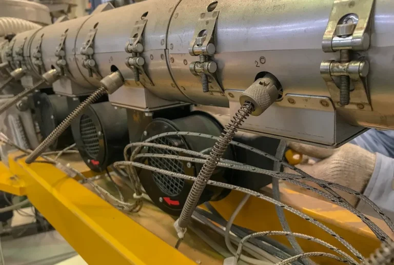
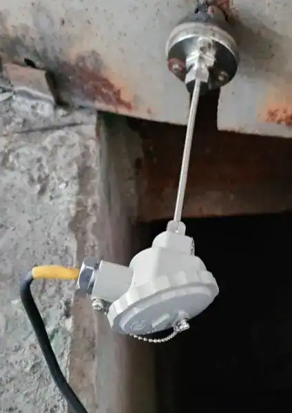
Running a 24 VDC loop supply cable or, worse, a 220 VAC solenoid feed through the same gland as the thermocouple pair raises the junction-box interior temperature by 5-15 °C above ambient. The CJC sensor reads that elevated temperature and compensates correctly for itself, but the compensating-wire-to-transmitter terminal joint is at a different (cooler) temperature, so you get a cold-junction gradient the CJC sensor cannot see. Symptom: 2-4 °C reading offset that appears only when the heated load is energized. I commissioned a Sinopec steam-cracker unit where this took six weeks to diagnose.
2. Sun load on outdoor junction boxes
A black-painted JB on a west-facing pipe rack hits 55-70 °C internal on a summer afternoon. Most IC CJC sensors are specced to ±0.5 °C across -40 to +85 °C, but manufacturers often quote ±0.3 °C at 25 °C and let the drift curve do what it does. Under-shade the junction box, or switch to an aluminum-housing JB painted light gray. Don’t fight physics.
3. Condensation on the CJC sensor PCB
Happens on outdoor installs where the JB is not properly sealed (IP65 compromised). Moisture on the sensor leads shifts the reading high by 1-3 °C, but only at night when the dew forms. Intermittent, seasonal, and maddening. Fix: replace gaskets, check breather vents, consider conformally coated electronics for coastal sites.
How Much CJC Accuracy Do You Really Need?
Not every loop needs the same CJC performance. Three rough tiers:
- Process monitoring, trending, alarms (boilers, HVAC, storage tank temperatures): ±0.5 °C CJC is plenty. Any modern transmitter clears this.
- Control loops on revenue-impacting processes (reactor feed, column reboiler, polymer extrusion): ±0.3 °C CJC matters. Pick a transmitter that specifies it, like the HMK HM100 at ±0.3 °C.
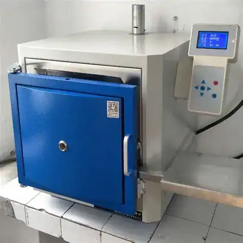
- Metrology, furnace uniformity surveys, calibration reference (AMS 2750, NADCAP compliance): ±0.1 °C CJC, and you’re probably looking at an ice-bath reference or a certified isothermal block instead of in-transmitter CJC.
For 90% of petrochemical plant loops, the tier-1 or tier-2 answer is correct. Engineers sometimes over-specify CJC because the datasheet number feels important; remember that your thermocouple wire is likely ±2.5 °C, so the loop accuracy can’t be better than that no matter how good the CJC is. If you’re still scoping the sensor itself, see how to select an industrial temperature sensor.
Frequently Asked Questions
Do I need cold junction compensation if my thermocouple cable runs straight to the DCS card?
Can I use an RTD instead of a thermocouple to avoid CJC entirely?
Why does my transmitter read wrong when I open the junction box cover?
Is CJC the same as linearization?
How often should CJC be calibrated?
Related reading: For the broader temperature-gauge primer covering definition, sensing types, and selection criteria, see Temperature Gauge: Definition, 5 Types, and Selection Guide.