TEMPERATURE INSTRUMENTATION TOOL
Thermocouple Calculator — mV ↔ °C (IEC 60584)
Convert thermocouple mV and temperature for Types K, J, T, N, E, S, R and B. The math comes straight from IEC 60584-1:2013 reference tables, with proper cold-junction compensation.
Home › Engineering Tools › Thermocouple Calculator
INPUT
RESULT
IEC 60584-1 Thermocouple Reference Table
All eight standard types in one view: range, tolerance, typical service. Numbers pulled straight from IEC 60584-1:2013 and ASTM E230.
| Type | Positive / Negative Leg | Range (°C) | Max EMF (mV) | Class 1 Tolerance |
|---|---|---|---|---|
| K | Chromel / Alumel | −200 to 1372 | 54.886 | ±1.5 °C or 0.4 % |
| J | Iron / Constantan | −210 to 1200 | 69.553 | ±1.5 °C or 0.4 % |
| T | Copper / Constantan | −270 to 400 | 20.872 | ±0.5 °C or 0.4 % |
| N | Nicrosil / Nisil | −270 to 1300 | 47.513 | ±1.5 °C or 0.4 % |
| E | Chromel / Constantan | −270 to 1000 | 76.373 | ±1.5 °C or 0.4 % |
| S | Pt-10 % Rh / Pt | −50 to 1768 | 18.693 | ±1 °C |
| R | Pt-13 % Rh / Pt | −50 to 1768 | 21.101 | ±1 °C |
| B | Pt-30 % Rh / Pt-6 % Rh | 0 to 1820 | 13.820 | ±3 °C (Class 2) |
How a Thermocouple Produces Millivolts
Take two wires of different metals, twist them together at one end, and you have a thermocouple. Heat that twisted end while the other end stays cool, and a small voltage shows up across the open end. That is the Seebeck effect, named after Thomas Seebeck who worked it out in 1821. How big the voltage gets comes down to two things: which metals you picked, and how far apart in temperature the hot tip and the open end sit.
A 100 °C gradient on a Type K gets you about 4.1 mV. Double the gradient to 200 °C, with the cold end pinned at 0 °C, and the signal roughly doubles too. IEC 60584-1:2013 pins down these values for every approved alloy pair. Those tables are what sit under this calculator.
Here is the catch. Those reference tables assume the cold junction sits at exactly 0 °C. Real plants do not work that way. Your terminal block might be 22 °C on a cool morning and 55 °C by lunch if the panel is baking in August sun. Correcting for that offset is cold junction compensation, or CJC. It is where most homebrew TC setups fall over. Lin Jun, who has been commissioning TC loops at Sinopec refineries since 1989, puts it this way: after wrong extension wire, bad CJC causes more reading errors than anything else.
The Eight Standard Thermocouple Types
IEC 60584-1 covers eight letter-designated types. Three of them (R, S, B) are platinum noble-metal. The other five (K, J, T, N, E) are base-metal alloys, and they handle roughly 95% of industrial work.
Type K (Chromel–Alumel) — if nobody tells you otherwise, this is what you use. It runs from −200 °C up to about 1260 °C continuous, gives around 41 µV/°C near 0 °C, stays affordable, and handles oxidising and neutral atmospheres fine. Its weak spot? Reducing or sulphur atmospheres strip chromium out of the Chromel leg, leaving it brittle and greenish. That failure mode has a name: green rot.
Type J (Iron–Constantan) handles reducing or inert atmospheres up to around 760 °C. Push it higher and the iron leg oxidises fast. It puts out more mV per °C than Type K, which is useful for low-voltage instruments. Watch the Curie point near 770 °C though: iron is magnetic, and the crystal-phase change there puts a kink in the curve that trips up engineers who forgot it was coming.
Type T (Copper–Constantan) owns the cold end. Best low-temperature linearity of any TC, reliable even in damp conditions, and the standard pick for food processing, pharma and HVAC work under 400 °C.
Type N (Nicrosil–Nisil) came out of Australia’s DSTO in the 1980s to fix what goes wrong with Type K above 1000 °C: green rot and drift. Expect to pay roughly 15% more than Type K at 2026 prices. What you get in return is noticeably better long-term stability in oxidising service between 1100 °C and 1260 °C. Kilns, furnaces, gas-turbine exhausts: that is where Type N quietly wins.
Type E (Chromel–Constantan) puts out more mV per °C than any other common type: about 68 µV/°C near 0 °C, roughly 60% higher than Type K. Good for sub-zero precision jobs where signal-to-noise matters. The ceiling is lower though, about 870 °C continuous.
Types S and R are platinum-rhodium. They take the high-temperature slot in oxidising atmospheres up to about 1600 °C. Type S (Pt-10%Rh/Pt) is the ITS-90 defining TC below the copper point. Type R (Pt-13%Rh/Pt) gives a bit more EMF. Both cost 20 to 40 times what a Type K costs, so you see them in calibration labs and on critical high-temp processes, not general plant service.
Type B (Pt-30%Rh/Pt-6%Rh) is for the very top end: 1500–1700 °C continuous, up to 1820 °C for short runs. It has a useful quirk. Below about 50 °C the output curve flattens out to near-zero EMF, which means you can skip cold junction compensation in most real installations. Hot terminal blocks that would wreck a Type K reading do not faze Type B.
Cold Junction Compensation Explained
The moment you wire a thermocouple’s leads to anything, you have two junctions. One is the hot tip out in the process. The other is wherever the TC leads meet your instrument, your terminal block. What you actually measure is the EMF difference between the two. IEC 60584-1 tables assume the cold junction sits at 0 °C, which goes back to the old days when engineers really did dunk reference junctions into an ice bath.
Modern transmitters handle this one of three ways. The CJC buttons on the calculator above map onto those three:
1. Manual CJ temp. You read the terminal-block temperature yourself with a separate sensor (usually a bead thermistor glued to the terminal strip) and type it in. The calculator converts that temperature into its EMF equivalent, adds it to your raw mV, then looks the total up on the IEC table. Lab-grade multimeters do exactly this. It is also the most accurate of the three.
2. Auto (0 °C ref). Tell the calculator the mV you pasted in has already been CJC-corrected upstream. You would use this if the number came from a smart transmitter like the HMK HM100, any ADT that runs CJC internally, or a PXI card with on-board compensation. In that case the mV is looked up straight against the IEC table.
3. None (raw). Mathematically the same as Auto. The difference is intent: you know the mV is raw and uncompensated, and you just want to see what the IEC table gives back for that exact number, no correction applied. Handy for sanity-checking a calibration mV source.
CJC error translates about 1:1. Miss the terminal-block temperature by 1 °C and your reading is off by about 1 °C. Panel rooms routinely swing 15 to 25 °C between a winter morning and a hot August afternoon. That is why Lin Jun takes a hand-held CJC reference block on every commissioning trip: a small Peltier-cooled terminal stub. Plug it into the loop and you have got a ground-truth reading to check against.
Thermocouple Wire Color Codes — IEC vs ANSI
Two color code standards are still in use. IEC 60584-3 covers Europe, China, most of Asia and South America. ANSI/MC96.1 covers North America, Saudi Aramco spec sheets, and a chunk of Middle-East EPC work. Under ANSI, the positive leg carries the type’s letter-color. Under IEC, you go by the outer sheath. This is the chart you will want on your phone during a rewire:
| Type | IEC 60584-3 Sheath | IEC + Leg | IEC − Leg | ANSI Sheath | ANSI + Leg |
|---|---|---|---|---|---|
| K | Green | Green | White | Yellow | Yellow |
| J | Black | Black | White | Black | White |
| T | Brown | Brown | White | Blue | Blue |
| N | Pink | Pink | White | Orange | Orange |
| E | Violet | Violet | White | Purple | Purple |
| S, R | Orange | Orange | White | Green | Black |
| B | Grey | Grey | White | Grey | Grey |
One rule worth memorising: in both standards, the negative conductor is always red or white, depending on the code. The positive is always a colour. Whatever your electrician’s habit from generic cabling, for thermocouples red is negative under ANSI/MC96.1. Flip it and your reading drops when the process heats up. That one is painful to diagnose from a desk.
Common Thermocouple Measurement Errors
Five failure modes cover most of the bad TC readings our field engineers run into during commissioning. If yours is drifting, jumpy, or plain wrong, work through these in order before you start pulling cable:
1. Wrong extension wire. Run plain copper between a Type K tip and your CJC terminal and every junction becomes its own small thermocouple. Calibration gone, spurious voltages added. Always match the extension or compensation wire to the type: KX for Type K, JX for Type J, and so on under IEC 60584-3.
2. Polarity reversed. Swapping + and − at the terminals is the single most common wiring error on new construction. The tell is obvious once you know it: reading drops when the process heats up. Fix it by reversing the two leads at the transmitter and verifying with a mV source.
3. Ground loop. Two grounded paths on the same TC circuit put 50/60 Hz hum on the signal that a lazy ADC cannot fully reject. Smart transmitters like the HM100 have strong common-mode rejection, but nothing is magic. Ground the TC at one end only, usually at the instrument.
4. Open or corroded junction. A sheathed TC in clean oxidising service will run 15 to 30 years. Put the same one in reducing or sulphur and you are measuring life in weeks. Resistance creeping up over months means the weld is on its way out. A reading that pins or floats is usually an open hot junction.
5. Calibration drift. A healthy Type K running above 1000 °C still drifts 0.5 to 2 °C every 1000 service hours. Plan on pulling the element once a year and comparing it against a calibrated reference in an oil bath or block calibrator. If drift crosses 0.5% of reading, retire it.
Sources and Standards
The reference tables used in this calculator are drawn from IEC 60584-1:2013 Thermocouples — Part 1: EMF specifications and tolerances and its companion tolerance document IEC 60584-2:1982. These are the governing international standards for thermocouple EMF characteristics and are harmonised with the NIST ITS-90 reference functions published at srdata.nist.gov/its90. North-American color codes follow ASTM E230/E230M; wire color per IEC 60584-3:2021.
This calculator is not a calibration instrument. Treat its output as engineering estimate, comfortably inside Class 1 TC tolerance. For trade, regulatory or SIL-loop work, use a traceable calibrator with documented procedure instead.
Frequently Asked Questions
Recommended Thermocouples from HMK
Ready-to-install sensors and HART-smart transmitters paired with this calculator. Calibrated to IEC 60584 in our ISO 9001 facility.
Related Engineering Tools
RTD Pt100 Calculator →
Platinum resistance thermometer: resistance ↔ temperature per IEC 60751, for PT100/PT500/PT1000 sensors and 2-, 3-, 4-wire configurations.
Pressure Unit Converter →
Ten common pressure units with bidirectional conversion — bar, psi, MPa, kPa, mbar, mmHg, atm and more.
4-20 mA Signal Calculator →
Convert current-loop signal values to engineering units, with linear scaling for any sensor range.
HMK Temperature Products
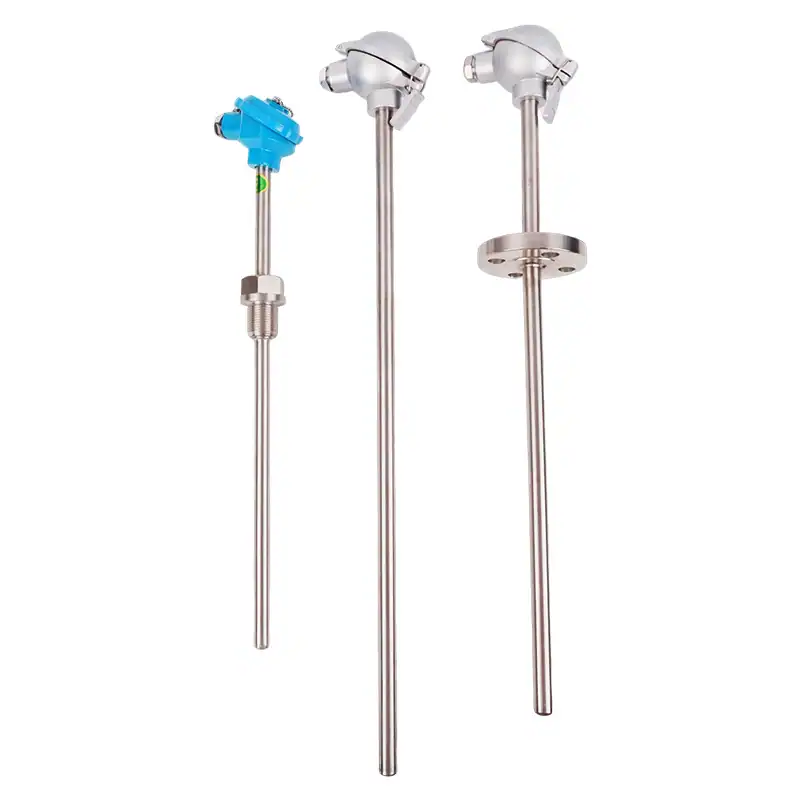
Sheathed Thermocouples →
Mineral-insulated K, J, T, N, E, S, R, B elements with Inconel, Incoloy or 316L sheaths up to 1600 °C.
Assembled Thermocouples →
Complete assemblies with thermowell, connection head and extension — ready-to-install for your process.
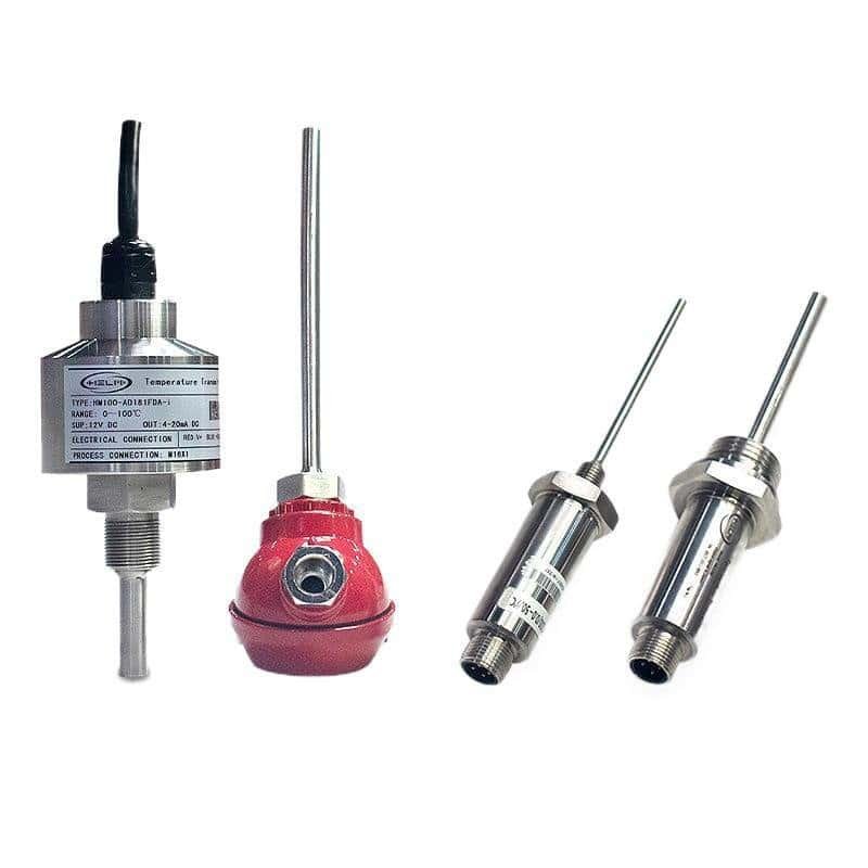
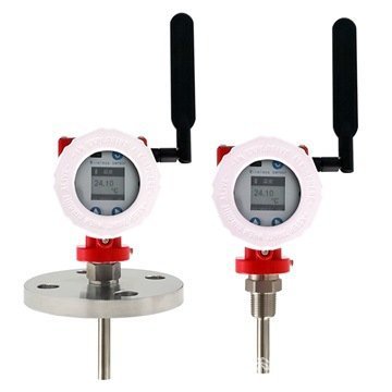
HM100 Temperature Transmitter →
HART-compatible smart transmitter with on-board CJC, PT100/PT1000/TC universal input and 4-20 mA output.
Temperature sensors and transmitters
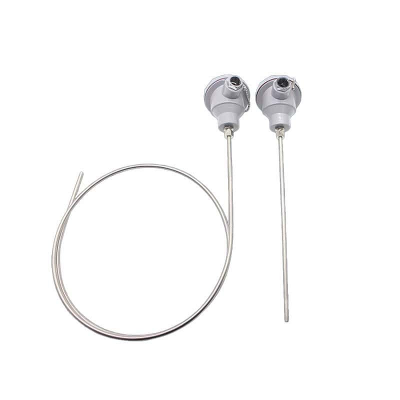
Sheathed Thermocouples
Sheathed thermocouples supplied in K, J, E, N and other calibrations.
View details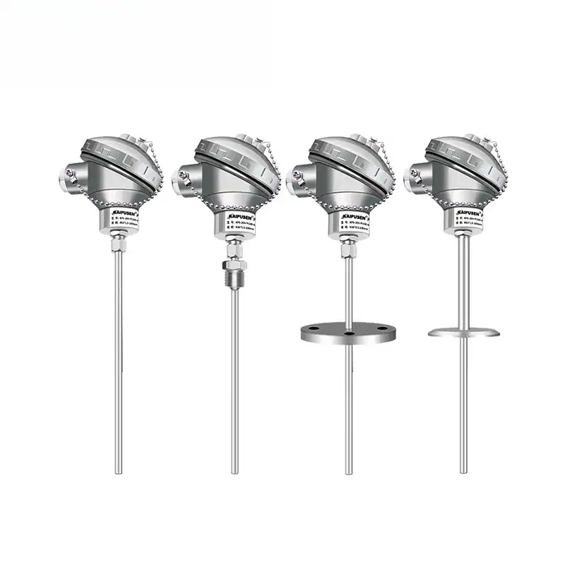
Sheathed RTD (Thermal Resistance)
Sheathed Pt100 RTD sensors for accurate mid-range temperature measurement.
View details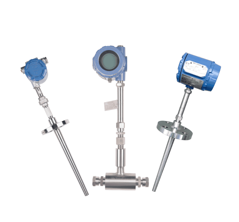
SBW Temperature Transmitter
Head-mounted temperature transmitter converting RTD or thermocouple input to 4–20 mA.
View details