HMK Temperature Sensors
Assembled Thermocouples
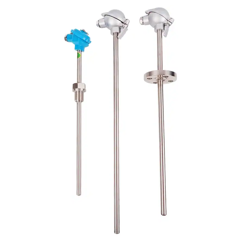
Modular assembled thermocouples with replaceable spring-loaded sensing elements for easy maintenance. Available in types K, N, E, J, T with protection tube diameters Ø16 and Ø20mm. 8 mounting configurations including screw thread, flange, pipe joint, and cone types. IEC 584 Class I & II certified.
Overview | Specifications | Selection Guide | Ordering Guide | Features | Applications | FAQ | Contact
Why Choose Assembled Thermocouples?
Assembled thermocouples are the workhorses of industrial temperature measurement, designed for demanding environments that require modular flexibility and easy maintenance. Unlike sheathed (mineral-insulated) thermocouples, assembled types feature a pressure-spring-loaded sensing element that can be quickly replaced without removing the protection tube from the process vessel, dramatically reducing downtime during scheduled maintenance.
HMK assembled thermocouples support five thermocouple types (K, N, E, J, T) covering temperature ranges from 0°C to 1200°C. The protection tube is available in stainless steel (1Cr18Ni9Ti, 0Cr25Ni20) for standard applications, or high-alumina ceramic for temperatures exceeding 800°C. With eight distinct mounting configurations — from non-fixed and screw thread to flanged, pipe joint, and cone types — there is a solution for virtually any industrial installation scenario.
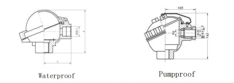
All models comply with IEC 584 and GB/T 30429-2013 standards. Standard models achieve thermal response time <90 seconds, while the fast-response G-suffix variants reduce this to under 24 seconds using a variable cross-section tube design. Waterproof (IP55) and splash-proof (IP65) junction box options ensure reliable performance in harsh environments.
Technical Specifications
| Parameter | Value |
|---|---|
| Thermocouple Types | K, N, E, J, T (per IEC 584) |
| Temperature Range | 0°C to 1200°C (type N/K max with high-alumina tube) |
| Tolerance Class I | ±1.5°C or ±0.004|t| (K, N, E, J); ±0.5°C or ±0.004|t| (T) |
| Tolerance Class II | ±2.5°C or ±0.0075|t| (K, N, E, J); ±1.0°C or ±0.0075|t| (T) |
| Protection Tube Diameter | Ø16, Ø20 mm (stainless steel); Ø16, Ø20 mm (high-alumina ceramic) |
| Protection Tube Material | 1Cr18Ni9Ti (0–800°C), 0Cr25Ni20 (0–1100°C), High-alumina ceramic (0–1200°C) |
| Thermal Response Time | <90s (standard), <24s (fast-response G suffix) |
| Element Configuration | Single or dual element (replaceable spring-loaded) |
| Insulation Resistance | ≥1000 MΩ (1m sample at 500V DC, 15–35°C, RH 45–75%) |
| Nominal Pressure | ≤4 MPa (screw/flange types); ≤15 MPa (cone thread type) |
| Junction Box | Waterproof (IP55) or Splash-proof (IP65) |
| Standards | IEC 584, GB/T 30429-2013 |
| Insertion Length | 150–2150mm (customizable) |
Temperature Range & Tolerance by Type
| Type | Graduation | Class I | Class II | ||
|---|---|---|---|---|---|
| Tolerance | Range (°C) | Tolerance | Range (°C) | ||
| WRN | K | ±1.5°C | -40 ~ +375 | ±2.5°C | -40 ~ +333 |
| ±0.004|t| | 375 ~ 1000 | ±0.0075|t| | 333 ~ 1200 | ||
| WRM | N | ±1.5°C | -40 ~ +375 | ±2.5°C | -40 ~ +333 |
| ±0.004|t| | 375 ~ 1000 | ±0.0075|t| | 333 ~ 1200 | ||
| WRE | E | ±1.5°C | -40 ~ +375 | ±2.5°C | -40 ~ +333 |
| ±0.004|t| | 375 ~ 800 | ±0.0075|t| | 333 ~ 900 | ||
| WRF | J | ±1.5°C | -40 ~ +375 | ±2.5°C | -40 ~ +333 |
| ±0.004|t| | 375 ~ 750 | ±0.0075|t| | 333 ~ 750 | ||
| WRC | T | ±0.5°C | -40 ~ +125 | ±1.0°C | -40 ~ +133 |
| ±0.004|t| | 125 ~ 350 | ±0.0075|t| | 133 ~ 350 | ||
Selection Guide by Installation Type
Choose the appropriate mounting configuration based on your process connection requirements, pressure rating, and installation constraints. The table below compares all 8 installation types to help you select the right model series.
| Installation Type | Series Code | Connection | Tube Φ | Pressure | Best For |
|---|---|---|---|---|---|
| 1. Non-Fixed | 1xx | None (friction fit) | Ø16/Ø20 | — | Open vessels, temporary measurement |
| 2. Fixed Screw Thread | 2xx | M27×2 / G3/4 | Ø16/Ø20 | ≤4 MPa | Standard pipe/vessel installations |
| 3. Movable Flange | 3xx | Adjustable flange | Ø16/Ø20 | ≤4 MPa | Vessels needing adjustable depth |
| 4. Fixed Flange | 4xx | Welded flange | Ø16/Ø20 | ≤4 MPa | Permanent high-pressure installations |
| 5. Adjustable Pipe Joint | 5x | M20×1.5 / NPT1/2 | Ø3–Ø8 | — | Small bore, adjustable depth |
| 6. Fixed Thread Cone | 6xx | M33×2 / NPT1 | Ø15 | ≤15 MPa | High-pressure fluid systems |
| 7. Straight Pipe Joint | 7x | M20×1.5 / NPT1/2 | Ø3–Ø8 | — | Straight pipe penetrations |
| 8. Fixed Threaded Pipe | 8x | M20×1.5 / NPT1/2 | Ø3–Ø8 | — | Permanent pipeline monitoring |
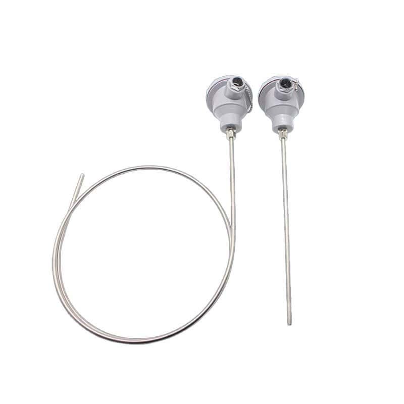
Non-Fixed Assembly Thermocouples (1xx Series)
High-alumina ceramic protection tubes for temperatures up to 1200°C. Available in both anti-spray (IP65) and waterproof (IP55) junction boxes.
| Model | Type | Range (°C) | Response | Tube Material | Ø (mm) | IP Rating |
|---|---|---|---|---|---|---|
| WRM-122 / WRN-122 | N / K | 0–1200 | <240s | High-alumina | Ø16 | IP65 |
| WRM-123 / WRN-123 | N / K | 0–1200 | Ø20 | IP65 | ||
| WRM-132 / WRN-132 | N / K | 0–1200 | Ø16 | IP55 | ||
| WRM-133 / WRN-133 | N / K | 0–1200 | Ø20 | IP55 |
Insertion lengths (L): 300×150 to 2150×2000 mm. Both single and dual element configurations available.
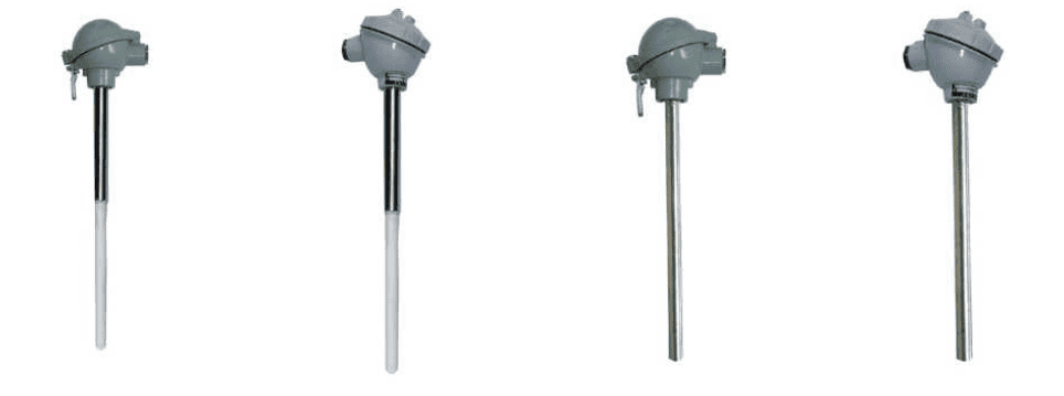
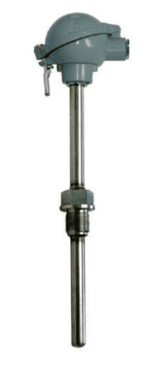
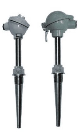
Fixed Screw Thread Thermocouples (2xx Series)
Most widely used configuration. M27×2 or G3/4 thread connection. Available in all five thermocouple types with standard or fast-response (G suffix) protection tubes.
| Model | Type | Range (°C) | Response | Tube Material | Ø (mm) |
|---|---|---|---|---|---|
| WRM-230 / WRM-230G | N | 0–800 / 0–1100 | <90s / <24s | 1Cr18Ni9Ti / 0Cr25Ni20 | Ø16 |
| WRN-230 / WRN-230G | K | 0–800 / 0–1100 | <90s / <24s | 1Cr18Ni9Ti / 0Cr25Ni20 | |
| WRE-230 / WRE-230G | E | 0–800 | <90s / <24s | 1Cr18Ni9Ti | |
| WRC-230 / WRC-230G | T | 0–350 | <90s / <24s | 1Cr18Ni9Ti | |
| WRF-230 / WRF-230G | J | 0–600 | <90s / <24s | 1Cr18Ni9Ti | |
| Ø20mm variants: WRM-231/231G, WRN-231/231G, WRE-231/231G, WRC-231/231G, WRF-231/231G — Same specs, Ø20mm tube, response <120s (std) / <24s (G) | Ø20 | ||||
IP55 waterproof (230/231 series). IP65 splash-proof variants: 220/221 series with same specifications. Thread: M27×2 (standard) or G3/4 (suffix A). Nominal pressure: ≤4 MPa. Insertion lengths: 150–2150 mm.
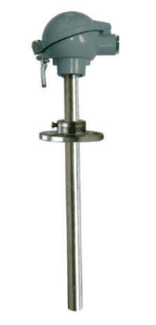
Flange Mount Thermocouples (3xx / 4xx Series)
Movable (3xx) and fixed (4xx) flange configurations. Both support five thermocouple types with Ø16/Ø20mm protection tubes. Nominal pressure ≤4 MPa.
| Configuration | Models (Ø16) | Models (Ø20) | Response (Std / Fast) | IP Rating | Lengths (mm) |
|---|---|---|---|---|---|
| Movable Flange | WR_-330 / 330G | WR_-331 / 331G | <90s / <24s | IP55 | 150–2150 |
| Fixed Flange | WR_-430 / 430G | WR_-431 / 431G | <90s / <24s | IP55 |
Fixed flange specifications: Ø16 flange D=Ø95, D1=Ø65, H=14mm; Ø20 flange D=Ø95(Ø105), D1=Ø65(Ø75), H=14(16)mm. Custom flanges available on request. IP65 anti-spray variants: 320/321 (movable) and 420/421 (fixed).
Cone Thread & Pipe Joint Thermocouples (5x/6xx/7x Series)
Specialized mounting configurations for high-pressure systems and small-bore applications.
| Type | Series | Connection | Tube Ø (mm) | Max Pressure | Lengths (mm) |
|---|---|---|---|---|---|
| Fixed Thread Cone | 620/630 | M33×2 / NPT1 | Ø15 | ≤15 MPa | 300×150 – 650×500 |
| Adjustable Pipe Joint | 53/53A | M20×1.5 / NPT1/2 | Ø3, Ø4, Ø5, Ø6, Ø8 | — | 245–1149 |
| Straight Pipe Joint | 73/73A | M20×1.5 / NPT1/2 | Ø3, Ø4, Ø5, Ø6, Ø8 | — | 245–1149 |
Pipe joint types: Protection tube materials 0Cr25Ni20 (N/K) and 1Cr18Ni9Ti (all types). Insertion depth should match thermowell U-tube dimension (see how to calculate insertion length U). Cone thread types: 620/620G = IP65, 630/630G = IP55.
Model Numbering & Ordering Guide
The model designation follows a systematic coding system. Specify each position to define your exact requirements.
| Position | Description | Options |
|---|---|---|
| W | Product type | W = Temperature instrument |
| R | Sensor type | R = Thermocouple |
| 3rd | TC material | N = NiCr-NiSi (Type K) | M = NiCrSi-NiSi (Type N) | E = NiCr-CuNi (Type E) | C = Cu-CuNi (Type T) | F = Fe-CuNi (Type J) |
| 4th | Element count | (none) = Single element | 2 = Dual element |
| 5th | Mounting type | 1=Non-fixed | 2=Screw thread | 3=Movable flange | 4=Fixed flange | 5=Pipe joint | 6=Thread cone | 7=Straight pipe | 8=Fixed pipe |
| 6th | Junction box | 2 = Anti-spray (IP65) | 3 = Waterproof (IP55) |
| 7th | Tube diameter | 0 = Ø16 std | 1 = Ø20 std | 2 = Ø16 high-alumina | 3 = Ø20 high-alumina |
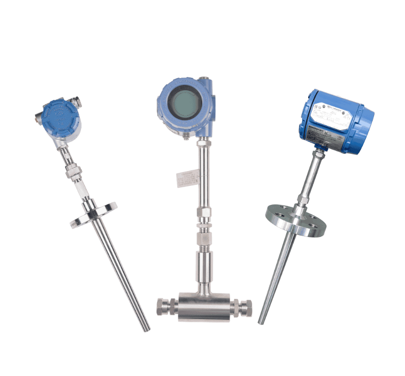
| Suffix | Additional | G = Fast response (variable cross-section) | B = With SBW temperature transmitter | A = BSP/NPT thread option |
Example: WRN-231G = Type K thermocouple, single element, fixed screw thread mount, waterproof junction box (IP55), Ø20mm standard tube, fast response. Specify insertion length L separately (e.g., L=300mm).
Key Features
Replaceable Sensing Element
Pressure spring-loaded design allows quick element replacement without removing the protection tube from the process. Reduces maintenance time from hours to minutes, cutting downtime costs.
8 Mounting Configurations
From non-fixed and screw thread to flanged, pipe joint, and cone types. Comprehensive mounting portfolio ensures compatibility with any process connection standard.
Fast Response Option (G Suffix)
Variable cross-section protection tube reduces thermal mass at the tip, achieving <24s response time compared to <90s standard. Available across all thermocouple types and mounting configs.
Wide Temperature Range
Covering 0°C to 1200°C with five thermocouple types. High-alumina ceramic tubes extend range beyond 800°C where stainless steel tubes reach their limits.
IEC 584 Class I & II Certified
Full compliance with international thermocouple standards. Class I tolerance as tight as ±0.5°C (Type T) ensures precision in critical process control applications.
Dual Element Configuration
Optional dual-element setup provides redundant measurement for safety-critical applications. Both elements housed in a single protection tube, saving nozzle space on vessels.
Industry Applications
Petrochemical & Refining
Reactor temperature monitoring, distillation column drums, cracking furnace control, and feed stream preheating. Fixed screw thread (2xx) and flange (3xx/4xx) mounts handle high-pressure process connections.
Power Generation
Boiler drum temperature, superheater outlet monitoring, economizer efficiency control, and steam quality assurance. Fast-response G-suffix models ensure rapid detection of temperature excursions.
Steel & Metallurgy
Reheating furnace zones, soaking pit temperature, rolling mill process control, and quenching tank monitoring. High-alumina ceramic tubes (1xx series) withstand temperatures up to 1200°C.
Cement & Building Materials
Rotary kiln temperature profiles, preheater tower zones, clinker cooler monitoring, and calcination process control. Non-fixed (1xx) configuration allows easy repositioning during maintenance.
Food & Pharmaceutical
Autoclave sterilization, pasteurization temperature, drying process optimization, and cooking vessel monitoring. Pipe joint types (5x/7x) with small Ø3–Ø8mm tubes fit standard sanitary fittings.
HVAC & Environmental
Large duct temperature measurement, stack gas monitoring, ambient air quality control, and heat recovery optimization. Multiple insertion lengths from 150mm to 2150mm cover any duct diameter.

Frequently Asked Questions
Need a Custom Assembled Thermocouple?
Our engineering team specializes in thermocouple solutions tailored to your exact process requirements. Contact us for custom tube materials, non-standard insertion lengths, special flange dimensions, high-volume pricing, or integrated transmitter configurations.
Our engineers typically respond within 12 business hours with detailed technical specifications and pricing.
Need to Convert Millivolts to Temperature?
If your assembled thermocouple reads in mV but your DCS expects °C — or vice-versa — our free engineering calculator handles all eight IEC 60584 types with manual or automatic cold-junction compensation, complete with CSV export for calibration records.