Thermowell Insertion Length: How to Calculate U for Any Pipe
On a thermowell data sheet, the insertion length U is the dimension most often filled in wrong. Set it too short and the sensor tip sits in the pipe-wall boundary layer, where the reading runs low and slow. Set it too long and the well fails the ASME PTC 19.3 TW-2016 wake-frequency check, and flow-induced vibration can snap the stem. Three minimum immersion rules and the standoff above them set U; the rest is arithmetic.
Quick answer: Insertion length U = immersion R + standoff S. Set R at half the pipe ID, raise it to the largest of three minimums (10× the tip diameter, the 50 mm / 2 in API floor, and sensing length + 25 mm liquid or + 75 mm gas), then add the wall, nozzle, and any insulation lagging. Round U up to a stocked well length and match the sensor stem.
Insertion Length, Immersion Length, and Lagging
Three dimensions appear on every thermowell order, and field crews routinely confuse two of them.
- Insertion length U runs from the tip to the underside of the process connection (thread, flange face, or weld). It is the number the data sheet asks for.
- Immersion length R runs from the tip to the point where the well enters the fluid. U is always equal to or greater than R.
- Lagging extension T is the added length between the process connection and the instrument head on an insulated line. It carries the head clear of the insulation.
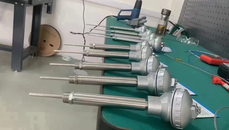
A fourth dimension, the sensor stem length S (the “L” dimension on an RTD or thermocouple), must match the well so the element seats at the bottom of the bore. The full breakdown of connection style, stem profile, and bore sits in our thermowell types and selection guide; this page computes the length.
The Three Minimums That Bound U
The largest of three minimums governs R; no single rule sets it alone. Each minimum protects a different failure mode.
| Rule | Value | What it protects |
|---|---|---|
| Tip position | Tip at 1/2 of pipe ID (1/3 to 2/3 acceptable); 1/2 of vessel ID | Reads bulk-stream temperature, not wall film |
| 10× tip diameter | R ≥ 10 × well tip OD | Limits stem-conduction error along the shank |
| API RP 551 floor | R ≥ 50 mm (2 in), perpendicular mount | Hard minimum immersion for accuracy |
| Sensitive length add | + 25 mm (1 in) liquid, + 75 mm (3 in) gas | Keeps the whole sensing element in the medium |
The mechanism behind the 10× rule is stem conduction: a short well drains heat from the tip out to the cooler flange, so the indicated value drifts below the true process temperature. We cover that error in the selection guide. For sizing, take it as a hard floor. ASME B40.9 and IEC 61520:2000 give the matching dimensional tables; API RP 551 sets the 50 mm (2 in) immersion floor.
Calculating U in Four Steps
The calculation converts a pipe size into a single U dimension.
- Set immersion R from tip position. R = f × ID, where f is the immersion fraction (0.5 typical) and ID is the pipe internal diameter.
- Raise R to the binding minimum. Compare R against 10× the tip diameter, the 50 mm (2 in) API floor, and the sensitive length plus 25 mm liquid or 75 mm gas. Take the largest.
- Add the standoff to get U. U = R + S, where standoff S = pipe wall + nozzle or coupling height + lagging T on insulated lines.
- Match the sensor stem. Specify element length so the tip seats at the bore bottom, then round U up to a stocked well length. Our 6 mm RTD assemblies seat a spring-loaded element against the bore bottom, which holds the 2.3 s response to a 50 °C step on the HMK data sheet.
Worked example A — DN100 (4 in) water line, threaded, no insulation.
Schedule 40 ID is 102 mm (4.0 in). At f = 0.5, R = 51 mm (2.0 in). The well tip is Ø10 mm, so the 10× rule demands 100 mm (3.9 in); the Pt100 element is 50 mm long, so the liquid add asks for 75 mm. The largest is 100 mm, so R rises to 100 mm. With a 6 mm wall and a 45 mm threadolet standoff, S = 51 mm (2.0 in), and U = 100 + 51 = 151 mm (5.9 in). Round to 150 mm, the minimum stocked length on our assembled thermocouples.
Worked example B — DN250 (10 in) gas line, flanged, 75 mm insulation.
Schedule 40 ID is 254 mm (10.0 in). At f = 0.5, R = 127 mm (5.0 in). The Ø13 mm tip sets a 130 mm (5.1 in) floor by the 10× rule, which governs. Standoff S = 9 mm wall + 100 mm flange nozzle + 75 mm lagging T = 184 mm (7.2 in). U = 130 + 184 = 314 mm (12.4 in). Specify L = 314 mm, or round to a 350 mm stocked length.
Both examples run into the same limit: in a 102 mm bore the 100 mm conduction floor nearly spans the pipe, so the tip lands at 98 % of the ID. DN100 is the practical floor for satisfying the 10× rule head-on. Anything smaller needs one of the methods below.
U Quick Reference by Pipe Size
The table lists immersion at the 1/2-ID tip position for Schedule 40 pipe, perpendicular mount. It is an engineering convention for first-pass sizing, not a code value; confirm every well against ASME PTC 19.3 TW-2016 before release.
| Nominal size | ID mm (in) | 1/2-ID immersion R mm | Sizing note |
|---|---|---|---|
| DN15 (1/2 in) | 16 (0.6) | 8 | Below all floors; use a small-line method |
| DN25 (1 in) | 27 (1.0) | 13 | Below 50 mm floor; small-line method |
| DN50 (2 in) | 53 (2.1) | 26 | Below 100 mm conduction floor; angle or swage |
| DN80 (3 in) | 78 (3.1) | 39 | Tight; 10× rule governs |
| DN100 (4 in) | 102 (4.0) | 51 | Practical floor for head-on mount |
| DN150 (6 in) | 154 (6.1) | 77 | Comfortable |
| DN200 (8 in) | 203 (8.0) | 101 | Comfortable |
| DN250 (10 in) | 254 (10.0) | 127 | Comfortable |
| DN300 (12 in) | 303 (11.9) | 152 | Comfortable |
| DN400 (16 in) | 381 (15.0) | 190 | Check wake frequency |
| DN600 (24 in) | 575 (22.6) | 287 | Long U; wake frequency often governs |
Small Lines: When the Minimum Will Not Fit
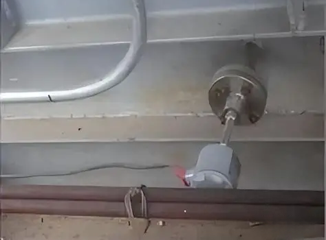
Below DN100, the 100 mm conduction floor will not fit a perpendicular well inside the bore. A DN40 (1.5 in) line has a 41 mm ID, and a vertical well reaching 100 mm would punch through the far wall. In the field on small-bore sample lines, we route the well through an elbow for exactly this reason. Three installation methods recover the immersion.
- Elbow, counter-flow mount. Install the well at a pipe elbow, pointing the tip upstream into the flow. The well runs along the pipe axis, so a 150 mm well gains its full immersion in a 40 mm line without touching the opposite wall.
- 45-degree angled entry. Mount the well through a 45-degree branch. The axial component stretches the wetted length: a 45-degree entry adds about 1.4× the radial depth, so a 41 mm radial path yields roughly 58 mm of immersion.
- Swaged spool. Swage a DN50 (2 in) line up to DN100 (4 in) at the measurement point, insert a standard perpendicular well, then swage back. We use this on clean utility lines where an elbow is not available near the control point.
For pipe-joint and cone mounts, the assembled-thermocouple insertion depth must match the well U dimension, a point our assembled thermocouples and RTD assemblies call out on the order sheet.
Before the PO: the Wake-Frequency Check
A longer U is not safer. Immersion raises accuracy, but it also lengthens the cantilever, lowers the well’s natural frequency, and moves it toward the vortex-shedding frequency of the flow. ASME PTC 19.3 TW-2016 sets the limit. When a long U fails the check, shorten U one step, increase the root diameter, or move to a stepped or helical-strake stem before giving up any immersion. Run the numbers in our wake-frequency walkthrough and the free wake-frequency calculator before the order goes out.
Need a thermowell sized for your line?
Send us the pipe size, service, and insulation. Our temperature team returns a U dimension with a matched assembled thermocouple or RTD and a test report.
Request a Quote Browse ThermowellsFrequently Asked Questions
What is the difference between insertion length and immersion length?
Insertion length U is measured from the tip to the underside of the process connection. Immersion length R is measured from the tip to the point of entry into the fluid. U is always equal to or greater than R, the difference being the standoff and any lagging extension.
How do I calculate thermowell insertion length?
Set immersion R at half the pipe ID, raise it to the largest of the three minimums (10× tip diameter, 50 mm API floor, sensitive length plus 25 mm liquid or 75 mm gas), then add the standoff and lagging to get U. Round up to a stocked length and match the sensor stem.
What size thermowell do I need for a 1-inch pipe?
A 1-inch (DN25) line has a 27 mm ID, too small for a perpendicular well to reach the 100 mm conduction minimum. Mount the well at an elbow facing upstream, use a 45-degree angled entry, or swage the line up to 4 inches at the measurement point.
What happens if the thermowell is too long?
A long insertion length lowers the well’s natural frequency and raises flow-induced vibration, which can fatigue and break the stem. ASME PTC 19.3 TW-2016 sets the wake-frequency limit; if U fails, shorten it one step or increase the root diameter.
How much length do I add for an insulated pipe?
Add the lagging extension T equal to the insulation thickness plus clearance for the head, typically 50 to 100 mm (2 to 4 in). T is part of the standoff S, so it raises U by the same amount without changing immersion R.