FREE ENGINEERING TOOLS
Thermowell Wake Frequency Calculator (PTC 19.3 TW-2016)
Run the four ASME PTC 19.3 TW-2016 checks on a thermowell before you ship the spec sheet. Plug in line velocity, geometry, and material; the calculator gives you Reynolds and Strouhal, vortex-shedding frequency, natural frequency, drag stress, oscillating stress, and a PASS or FAIL on each of the four design gates. For the physics behind every step, see the companion thermowell wake frequency calculation guide. For thermowell selection by service, see our thermowell catalog.
Calculator
Process Conditions
Thermowell Geometry
Material (Properties at Design Temperature)
Computed Values
First-pass sizing only. The full PTC 19.3 TW-2016 procedure includes Helmholtz frequency check, partial penetration weld evaluation, and Murdock mounting correction factors that this tool simplifies. For an issued spec sheet, run the official Ashcroft or WIKA calculator with full dimensional verification. Material properties are typical values at the listed design temperature; on a real project, pull S_y and S_a from ASME Section II Part D at your exact line temperature.
How the Four Checks Hang Together
The calculator above is shaped around the four design gates PTC 19.3 TW-2016 puts on every thermowell. Skip any one of them and you can ship a well that calibrates fine on a workshop bench, then snaps off three months into service. We have seen this happen on a fired-heater pass crossover where the bench-tested 304 well saw 75 m/s gas, sat right under fw / fn = 0.83, and fractured at the root weld after the unit lined out.
Walking through the chain: line conditions give you Reynolds, which fixes Strouhal, which gives the vortex shedding frequency fw. Geometry and material give the well its natural frequency fn. The first gate says fw must stay clear of fn. The drag from steady flow gives σ_d at the root; the lift swing from vortex shedding gives σ_max once dynamic amplification near resonance kicks in. The last gate says the bore-and-pressure stress σ_p must stay inside what the material can carry under steady static load. Every gate uses your real numbers, not a textbook value.
The 4 PTC 19.3 TW-2016 Stress Checks, Plain Language
1. Frequency limit: fw / fn < 0.8
The Strouhal vortex sheds off the well at fw = St · V / B. The well wants to vibrate at its own fn, set by geometry and material. When the two meet, the well rings, and high-cycle fatigue starts. PTC 19.3 keeps a 20 % safety margin: fw must stay under 0.8 · fn for the transverse mode. If you sit close to the limit on a velocity that already swings 10 to 15 % through the day, you are on borrowed time.
2. In-line vortex: fw / fn < 0.4
Most online tools only check the transverse gate. On high-velocity gas lines, the well also vibrates parallel to flow at half the Kármán frequency, and the in-line cracks initiate at the weld toe long before transverse fatigue shows. PTC 19.3 calls this out separately. If your ratio sits between 0.4 and 0.8, the design is legal but you should add a helical strake or shorten the well.
3. Dynamic (oscillating) stress σ_max < S_a
The vortex lift force is roughly 60 % of drag, swung up by a dynamic magnification factor DMF that climbs sharply as fw / fn approaches 1. The calculator uses DMF = 1 / (1 − r²) for r < 1. Even at r = 0.5, the lift stress is already 1.33× its static value. S_a is the material’s allowable cyclic stress at the design temperature, pulled from ASME Section II Part D fatigue curves. For 316L at 540 °C, S_a sits near 52 MPa; at room temperature it is roughly 138 MPa, so a well that passes on a workshop bench can still fail in service.
4. Static and pressure stress σ < 0.667 · S_y
Two separate stress paths share the same allowable. The drag from steady flow bends the well as a cantilever, putting σ_d at the root. The line pressure pushes outward on the wall around the bore, giving σ_p from the Lamé thick-wall expression. Both must stay under 0.667 · S_y, which is the PTC factor of safety against yield. On hot service, the yield strength S_y drops fast: A105 carbon steel is 250 MPa at room temperature and 130 MPa at 425 °C. The same well that holds 25 MPa drag at start-up sees the allowable shrink underneath it as the line heats up.
Strouhal Number by Reynolds Range
The calculator picks Strouhal from this piecewise table, which follows the PTC 19.3 TW-2016 fit to circular-cylinder vortex data. The plateau at St ≈ 0.22 is the value most textbooks give. On real industrial flows you cross out of that plateau at both ends, and PTC 19.3 nudges the value up in the high-Re regime where most steam and gas lines actually sit.
| Reynolds Re | Strouhal St | Typical service |
|---|---|---|
| < 1 000 | 0.180 | Slow process liquids, viscous oil |
| 1 000 to 200 000 | 0.220 | Subcritical plateau, most water and low-velocity gas |
| 200 000 to 500 000 | 0.226 | Transition, mid-velocity steam and process gas |
| 500 000 to 1 000 000 | 0.230 | High-velocity superheated steam, fuel gas headers |
| > 1 000 000 | 0.240 | Trans-critical, large gas pipelines and turbine inlets |
Material Property Reference (at Design Temperature)
The preset dropdown loads typical values at the listed design temperature. They are good enough for a first-pass sizing. For an issued spec sheet, pull modulus and yield from ASME Section II Part D at your exact line temperature, and S_a from the matching fatigue curve in Section VIII Division 2 Annex 3.F. The biggest field mistake we still see on submittals is using room-temperature values for a 540 °C steam well, which understates the cyclic stress check by a factor of two or more.
| Material | E (GPa) | ρ_m (kg/m³) | S_y (MPa) | S_a (MPa) | Design T (°C) | Typical service |
|---|---|---|---|---|---|---|
| 316L SS | 138 | 8000 | 116 | 51.7 | 540 | Steam, refinery, general process |
| 304 SS | 138 | 7900 | 110 | 48.3 | 540 | Water, steam, mild process |
| Carbon Steel A105 | 145 | 7850 | 130 | 27.6 | 425 | Steam header, low-temp gas, cheapest option |
| Inconel 600 | 175 | 8430 | 207 | 68.9 | 540 | High-temp gas, fired heaters |
| Inconel 625 | 178 | 8440 | 290 | 79.3 | 540 | Creep service, exhaust, gas turbines |
| Hastelloy C-276 | 172 | 8890 | 220 | 78.6 | 540 | Severe chloride and acid service |
| Monel 400 | 140 | 8800 | 105 | 41.4 | 425 | HF alkylation, seawater, brine |
Related Tools and Guides
- The physics deep-dive: Thermowell Wake Frequency Calculation: 6-Step Field Guide
- Element first, assembly second: How to Select an Industrial Temperature Sensor
- Element comparison: RTD vs Thermocouple and Thermocouple Type Selection
- Output and signal: 4-20 mA Wiring Guide
Frequently Asked Questions
What is PTC 19.3 TW-2016 and why does my thermowell need to pass it?
ASME PTC 19.3 TW-2016 is the U.S. performance test code that defines how to check a thermowell for vortex-induced vibration and stress. It is the standard piping and instrumentation specifications point to when they ask for a wake frequency calculation. If your spec sheet says “PTC 19.3 compliant,” you need the four checks in this calculator to come back green, with backup math from the official Ashcroft or WIKA tool before the well leaves the workshop.
Why 0.8 and not 1.0 for the frequency ratio?
0.8 is the PTC 19.3 safety margin against drift in real service. Velocity changes through the day, sensor mass changes when you swap an RTD for a transmitter-style probe, and temperature drops the natural frequency by 10 to 15 % from cold to hot. The 0.8 limit keeps you out of the resonance ramp even when several of these stack against you.
What if my well fails the frequency check?
You have three routes. Shorten the unsupported length, which raises fn (the cheapest fix if the immersion is generous). Increase the root diameter A, which also raises fn but costs more material. Or wrap the stem with a helical strake to break up vortex shedding, which is the standard fix on high-velocity gas service. For most steam and water lines the shortening route works; for combustion-air ducting or gas turbine inlets the strake is usually the right answer.
Do I need to correct E and S_y for my exact line temperature?
For a first-pass calculation, the preset values get you to within 10 to 15 % of the real number. For an issued spec sheet, yes. Modulus E drops 25 to 30 % from room temperature to 540 °C for stainless steels, which directly lowers fn. Yield S_y drops 30 to 45 % over the same range, which tightens the static check. The calculator lets you override every material field, so paste the ASME Section II Part D value for your exact T into the form.
How does this compare with the WIKA or Ashcroft calculator?
The four gates are the same; the simplifications are not. This tool uses a fixed clamped-free mode shape for fn, a 0.6 lift-to-drag ratio for the oscillating force, and the piecewise Strouhal table above. The vendor tools include the Murdock mounting correction (which shifts fn by 5 to 8 %) and a more detailed Helmholtz check for the air column inside the bore. Use this calculator to size during design and to sanity-check whatever the vendor returns. For the issued spec sheet, run the vendor tool.
Is there a Chinese national standard equivalent to PTC 19.3 TW-2016?
Yes. GB/T 30121-2013 covers thermowells for industrial platinum and copper resistance thermometers, and uses the same Reynolds-Strouhal-frequency framework with slightly different scope. Symbol naming differs (immersion length instead of unsupported length, vortex-shedding frequency instead of wake frequency), but the calculation flow lines up one-for-one. On bilingual EPC projects we hand teams a symbol map; the calculator above is the PTC labelling.
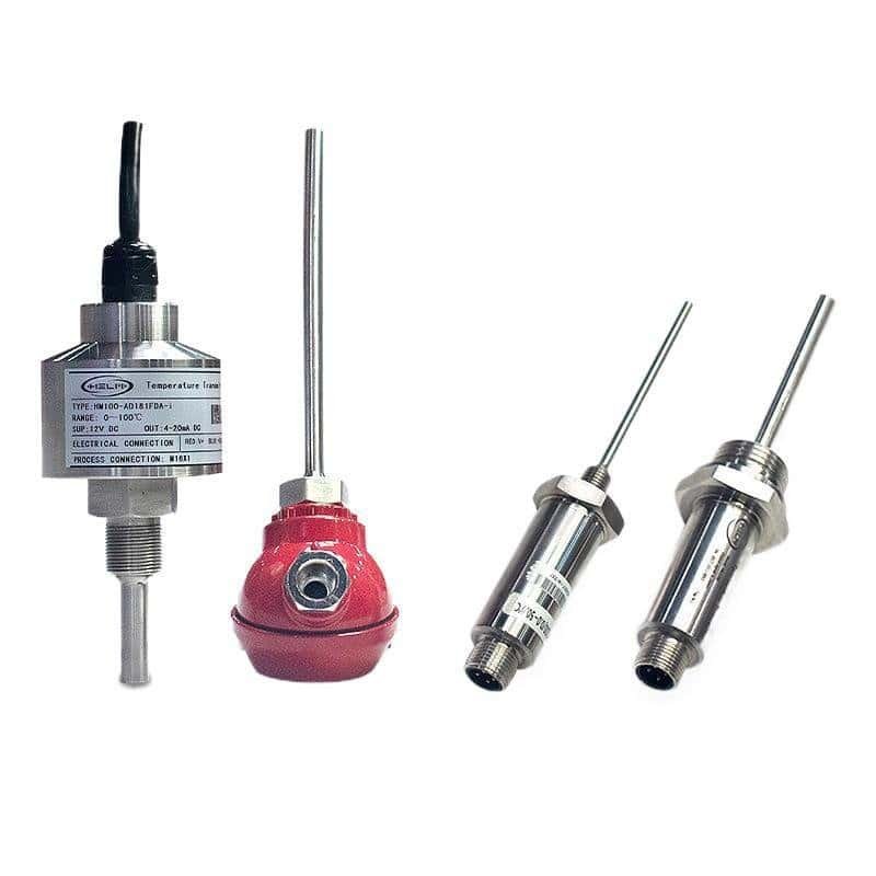
Recommended HMK Products
The wake frequency check sizes the protection tube. These are the matching HMK temperature instrument and signal-output products to fit inside it.
Recommended Reading
Three companion guides that explain what the calculator does and how it fits into a thermowell spec sheet.
- Thermowell Wake Frequency Calculation: 6-Step Field Guide — the physics behind every input above, with a worked example on a 540 °C main steam line.
- How to Select an Industrial Temperature Sensor — pick the sensing element first, then the assembly. Pairs with the material reference table on this page.
- RTD vs Thermocouple — the element that goes inside the thermowell. Which one wins by temperature, accuracy, and response time.
Standards and References
The four-gate framework in this calculator follows ASME PTC 19.3 TW-2016 (Thermowells). Material allowable stresses are typical values consistent with ASME BPVC Section II Part D Tables 1A, 1B, and 5A. For the U.S. reference treatment of vortex-induced vibration in cantilever cylinders, see NIST publications on bluff-body wake. The Chinese equivalent for thermowells used with RTDs is GB/T 30121-2013. Vendor calculators we cross-check against include the WIKA Wake Frequency Calculation tech info and the Ashcroft thermowell line.
Selecting a thermowell? See our guide on how to choose the connection, stem, material and insertion length.
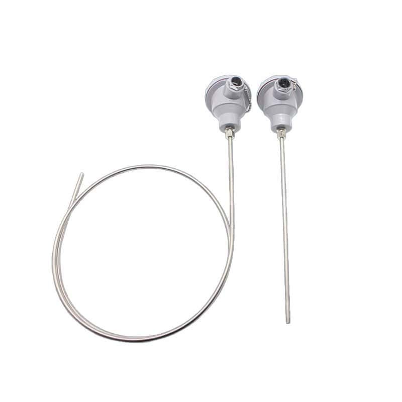
Temperature sensors for thermowell installation
Sheathed Thermocouples
Sheathed thermocouples supplied in K, J, E, N and other calibrations.
View details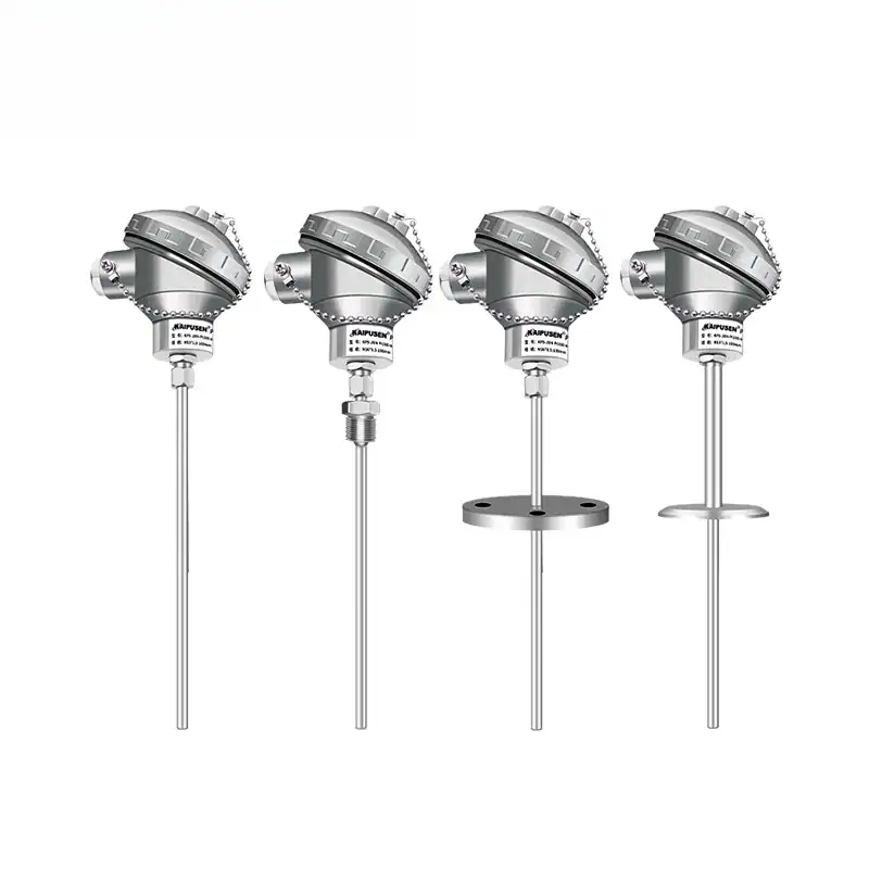
Sheathed RTD (Thermal Resistance)
Sheathed Pt100 RTD sensors for accurate mid-range temperature measurement.
View details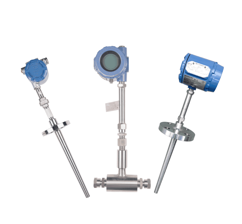
SBW Temperature Transmitter
Head-mounted temperature transmitter converting RTD or thermocouple input to 4–20 mA.
View details