Thermocouple Extension Wire vs Compensating Cable: Which One Fits Your Loop
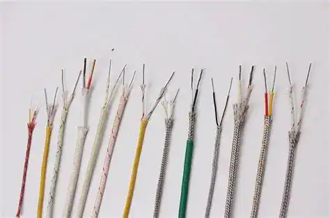
Choose the wrong cable between the thermocouple head and the transmitter, and a 0.75 % class-A probe becomes a 2–3 °C system. Extension wire and compensating cable look identical in a catalog shot and share the same two-letter color codes. They are not interchangeable.
The difference shows up as a two-letter jacket print in a supplier catalog — KX versus KCA — but in a live 4–20 mA loop it shows up as drift the transmitter cannot filter out. What follows is field data from HMK bench rigs, commissioning notes from refinery, food-plant and utility loops, plus the five wiring habits that bury more error in a reading than the sensor ever could.
What Extension Wire and Compensating Cable Actually Do
A thermocouple only generates an EMF at the junction where the two alloys meet — the hot junction. To read that EMF accurately, the cold reference junction has to sit somewhere temperature-controlled: a transmitter input, a head enclosure, an ice-point block. Between hot junction and cold junction can be 20 cm or 100 m.
Extension wire and compensating cable are the two ways to carry the hot-junction EMF back to the reference point without introducing an unwanted second thermocouple at every terminal.
Extension wire does this with the same two alloys as the sensor — a Type K probe runs into KX cable that is also chromel/alumel. Compensating cable uses a different, cheaper alloy pair chosen so the Seebeck curve matches the sensor only inside the narrow ambient window where the terminal junctions sit. Outside that window, the match breaks.
The Core Difference: Same Alloy vs Equivalent EMF
Extension grade is identical alloy. The cable is thermocouple wire in a different jacket. A KX extension cable carries the same chromel/alumel pair as the probe, so the EMF curve is linear and matches across the full −40 °C to 1200 °C Type K range.
Compensating grade substitutes one or both conductors with an alloy that produces a similar EMF only in the ambient band the terminal junctions see — typically 0 °C to 100 °C or 0 °C to 200 °C depending on the class. A KCA compensating cable uses iron and copper-nickel alloys that mimic chromel/alumel within that narrow window.
The payoff shows up on noble-metal sensors. On Pt-Rh R and S types, extension wire means buying platinum and rhodium by the meter — compensating grade swaps those for copper and copper-nickel at a fraction of the cost, so cable budgets stop hurting.
The trade-off: if the terminal box runs hot — above the compensating cable’s rated window — the EMF match breaks down and extra error appears at the cold junction.
GB, ANSI and IEC Codes Decoded
Buyers sourcing from Asian, American and European suppliers constantly hit mismatched two-letter codes for the same cable. Short version: first letter is the TC type, second letter tells you what the cable is.
| TC type | Extension (same alloy) | Compensating (equivalent EMF) | IEC 60584-3 jacket |
|---|---|---|---|
| K | KX (GB, ANSI) | KCA / KCB (GB, ANSI) | Green |
| J | JX (GB, ANSI) | — (rare) | Black |
| T | TX (GB, ANSI) | — (rare) | Brown |
| E | EX (GB, ANSI) | — (rare) | Violet |
| N | NX (GB, ANSI) | NC (GB, ANSI) | Pink |
| R / S | SX / RX (ANSI — rare) | SC / RC (GB/T 4989); SCA / SCB / RCA / RCB (ANSI MC96.1) | Orange |
| B | — | BC (GB, ANSI) | Grey |
GB/T 4989-2013 and ANSI MC96.1 use the same letter-pair format for base-metal types (K, J, T, E, N) — the codes line up directly. Noble-metal compensating grades are where the two diverge: GB uses single-class codes (SC, RC), while ANSI splits them into EMF-class variants (SCA / SCB for slightly different mV-vs-temperature curves). When a project sources hardware from multiple regions, cross-check every letter-pair against the IEC 60584-3 thermocouple wire color code on the jacket. For the underlying EMF values each code is certified against, the NIST ITS-90 thermocouple reference tables are the authoritative source.
Temperature Ratings and Insulation Classes
Continuous temperature limit is set by the jacket, not the conductor.
| Insulation | Continuous °C | Short-term °C | Typical use |
|---|---|---|---|
| PVC | −20 to 105 | 125 | Indoor control rooms, panel runs |
| PFA (Teflon) | −65 to 250 | 300 | Clean-process zones, food and pharma plants |
| Fiberglass (FG) | −60 to 400 | 480 | Furnace peripherals, kiln yards |
| Silicone-sheathed braid (SSB) | −60 to 200 | 250 | Flexible offshore tray |
| Ceramic-fiber / MI | up to 650 | 800 | Direct-heat zones, gas turbine bays |
Put the wrong jacket into a hot tray and the insulation melts long before the conductor hits its limit.
Decision Flow: Which One Fits Your Loop
Four questions, in order:
- Sensor type? If it is Pt-Rh (R, S, B) — start with compensating grade. Extension wire on noble-metal types is almost never economically justified.
- Terminal-junction ambient max? If the field junction box climbs above 200 °C, compensating cable’s EMF match breaks — switch back to extension grade or reroute the junction.
- Run length? Over ~30 m on a base-metal TC, resistance-induced error on 20 AWG compensating cable starts to matter for 0.4 % control. Use extension grade or step up to 16 AWG.
- Budget pressure on large skid counts? On 40+ identical base-metal (K / J / T) loops, compensating cable rarely pays back the extra wiring risk — stay with extension grade.
Defaults: base-metal TC (K, J, T, N) running 10–30 m indoors → extension grade. Pt-Rh probe → compensating grade.
Field Data: Loop Resistance, Length and Error
Resistance-induced voltage drop on an extension or compensating run translates almost directly into a temperature error. Below is loop-test data from an HMK bench rig held at 600 °C hot-junction, reading into a 10 MΩ-input transmitter at 25 °C ambient.
| TC | Cable grade | AWG | Ω/m (loop) | 30 m error | 60 m error | 100 m error |
|---|---|---|---|---|---|---|
| K | KX extension | 20 | 0.22 | ±0.4 °C | ±0.8 °C | ±1.4 °C |
| K | KCA compensating | 20 | 0.18 | ±0.5 °C | ±1.0 °C | ±1.7 °C |
| J | JX extension | 20 | 0.36 | ±0.5 °C | ±0.9 °C | ±1.5 °C |
| S | SC compensating | 20 | 0.12 | ±1.2 °C | ±2.3 °C | ±3.8 °C |
| K | KX extension | 16 | 0.09 | ±0.2 °C | ±0.3 °C | ±0.5 °C |
Twenty-two ohms of loop resistance on a 100 m KX run looks alarming by the old 2.2 Ω/m rule, but it is a non-issue for any modern 10 MΩ-input transmitter — the old rule was sized for 1 kΩ-input analog recorders and has not been updated. The real length sensitivity is on Pt-Rh S-type, where the Seebeck coefficient is tiny (~6 μV/°C at 600 °C), so every milliohm shows up at the reading. Stepping up one AWG almost always costs less than halving the run, which is why long pulls should be specified at 16 AWG from the start rather than re-pulled under a commissioning deadline.
Five Wiring Mistakes That Push Error Past 1 °C
Polarity reversal. Hook KX+ to the transmitter− terminal and the loop reads ambient instead of hot-junction. Always confirm the red conductor. In GB/T and IEC, red = negative on thermocouple cable — the opposite of almost every other cable type, and it trips up electricians constantly.
Mixed grades in one run. A spliced tray with 20 m of KX extension and 20 m of KCA compensating introduces a third thermocouple at the splice whenever that junction runs above ~100 °C. Pick one grade end-to-end.
Unshielded near VFDs. A drive cabinet produces enough common-mode noise to shift a 41 μV/°C K-type signal by 2–5 °C. Shielded twisted-pair, grounded at the transmitter end only, is mandatory in any drive-populated space. Loop-side grounding is separate from the sensor tip — see grounded vs ungrounded thermocouple junction for how the sensor-end choice affects ground-loop rejection.
Transposition at junction boxes. If both conductors swap at an intermediate terminal block, the error cancels — unless the two blocks sit at different temperatures. Always wire through, never loop back.
Copper for the last meter. Using plain copper on the final 500 mm because “it’s only a short piece” inserts a cold junction at the terminal block. Even 500 mm creates measurable error when the panel warms above ambient. Run the specified cable all the way into the transmitter terminal.
HMK Thermocouple and Transmitter Options
Pick the probe by process first. Cable grade is a secondary spec, driven by junction-box ambient and run length — not by the sensor choice. Every probe in the HMK line terminates in a standard head that accepts any X or C grade cable directly.
- Assembled Thermocouples — Type K, J, T, E, N probe in a protection tube with DIN B or NPT terminal head; the default sensor for base-metal loops under 100 m paired with KX / JX / TX extension cable.
- Sheathed Thermocouples — mineral-insulated (MI) probe good to 1100 °C; bendable, vibration-tolerant, and the usual partner to compensating cable on furnace and boiler loops.
- Multi-Point Thermocouples — 2 to 40 measuring points on one stem for reactor bed profiles and large tanks; each channel lands on its own compensating-cable terminal.
- Explosion-Proof Thermocouples — NEPSI-certified probe and enclosure for Zone 1/2 and Zone 21/22 areas; pairs with the same KX or compensating cable as the standard line inside a flameproof junction box.
- HM100 Temperature Transmitter — head-mounted universal TC / RTD input with 4–20 mA or HART output; terminates any X or C grade cable directly at the probe head and eliminates one splice point.
→ See the full temperature sensors and transmitters range.
Frequently Asked Questions
No. Plain copper inserts an unwanted cold junction at every terminal block and turns the reading into a rough ambient-offset estimate. Use KX or KCA from head to transmitter.
For K-type 20 AWG KX into a 10 MΩ-input transmitter, usable length before resistance error exceeds ±1 °C is around 80–100 m. For noble-metal SC or RC, stay under 30 m or step up to 16 AWG.
Yes. Reversed polarity produces a reading roughly equal to ambient minus process temperature — a clearly wrong value that is nevertheless easy to misread as a sensor failure. Verify with a color or magnet check: in GB and IEC, the red conductor is negative on TC cable.
On Pt-Rh R, S and B types, yes — compensating can be a small fraction of extension-grade cost because it avoids platinum and rhodium conductors. On K, J, T and N types the price gap is narrow, so extension is the default.
Check the jacket print (GB/T 4989-2013 mandates the code), magnet-test the conductors (KX negative is magnetic, KCA is not), or bench-test at 200 °C terminal ambient — KCA drifts while KX stays linear.
Related reading: see when to put the transmitter at the head to save compensation cable — a seven-criterion decision guide for picking head mount or DIN rail temperature transmitters.
Related reading: the analogous decision on the pressure side: pigtail siphon vs condensate pot — when and how to spec a steam pressure trap, with sizing math and material selection.