High Temperature Pressure Transducer: 4 Proven Methods from 250°F to 2192°F (and How to Pick Yours)
A pressure transducer (also called a pressure sensor for high temperature service when the application sits above the standard +185°F / +85°C limit) that holds calibration on a 70°F bench can drift 5% — or fail outright — when its diaphragm sees 600°F process media. Most spec sheets quote a “compensated temperature range” that ends at 185°F (85°C), yet real industrial processes routinely run hotter: superheated steam, molten polymers, hot oil heat-transfer loops, autoclaves, engine test cells, downhole tools.
On sticky, crystallizing, or sanitary media the flush form factor matters as much as the temperature rating; see our flush diaphragm pressure transducer guide.
Measuring the difference between two hot pressures, such as orifice flow or column ΔP, is a two-sided problem; we cover it in the high-temperature differential pressure transmitter guide.
For HMK hardware, the ceramic-capacitive HM26 covers most high-temperature lines, while the heat-pipe-isolated HM80 extends the range further.
The fix is not “buy a sensor rated higher.” Above 250°F (121°C), there is no single chip technology that wins. Instead, four distinct engineering methods dominate the market — and choosing the wrong one quietly costs you accuracy, sensor life, or a whole production batch.
This guide compares those four methods head-to-head, gives the temperature ranges each one realistically owns, and shows where HMK-TECH’s standard products land — including custom builds rated up to +2192°F (+1200°C).
What Counts as a “High Temperature” Pressure Transducer?
For most general-purpose pressure transducers, the manufacturer publishes two separate temperature limits:
- Compensated temperature range — the band where the published accuracy spec holds (typically -4°F to +185°F / -20°C to +85°C).
- Operating media temperature — the maximum the wetted parts can survive without failing, but with degraded accuracy.
A high temperature pressure transducer — also written as a pressure sensor for high temperature service — is one engineered so the media temperature limit is meaningfully above the compensated range, and the thermal error is specified across that wider window. As a working definition used by ISA practitioners and most industrial buyers:
Process media above +185°F (+85°C) — and especially above +250°F (+121°C) — pushes you out of standard catalog territory and into purpose-built high temperature designs.
Below that threshold, almost any quality transmitter will work. Above it, the choice of method matters more than the brand on the label.
Why Standard Pressure Transducers Fail Above 250°F
Three failure modes dominate, and each one points to a different design choice.
1. Sensing-element drift. Diffused-silicon piezoresistive chips — the workhorse of the industry — are doped semiconductors. As junction temperature rises, carrier mobility shifts, span output drifts, and at roughly +257°F (+125°C) the silicon-glass bond begins to creep. Above +302°F (+150°C), drift is no longer linear and software compensation cannot fully recover it.
2. Seal and fill-fluid degradation. Most general-purpose transmitters use NBR (Buna-N) O-rings, good only to about +212°F (+100°C). FKM (Viton) extends this to roughly +392°F (+200°C). Above +500°F (+260°C), only PTFE or all-metal seals survive. The internal fill fluid behind isolation diaphragms has its own ceiling — silicone oils typically tap out around +572°F (+300°C), at which point vapor pressure distorts readings.
3. Electronics damage. ASIC signal conditioners, surface-mount capacitors, and EEPROMs sitting inside the transmitter housing are rated to +185°F (+85°C) ambient. Direct mounting onto a hot pipe conducts heat right into the electronics. The element may survive — the amplifier will not.
Any high temperature design has to address all three. The four methods below each solve them differently.
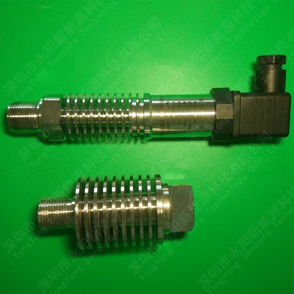
Method 1 — Cooling Stand-Off / Heat-Pipe (Up to ~+662°F / +350°C)
The most economical and most widely deployed method. A finned tubular extension between the process connection and the sensor body uses natural convection to dissipate heat before it reaches the sensing element. The process tap stays at full temperature; the sensor itself runs at +185°F (+85°C) or below, so a conventional diffused-silicon element can be used.
Strengths: standard accuracy (±0.25% FS or better), mature manufacturing, rugged 316L stainless wetted parts, no exotic materials. The thermal time constant is short enough for slow-changing process control loops.
Trade-offs: the stand-off adds 4–8 inches of length and needs free air around the fins. It is unsuitable for low-frequency dynamic measurement (the long impulse line attenuates fast pressure transients) and the cooling fins must not be insulated.
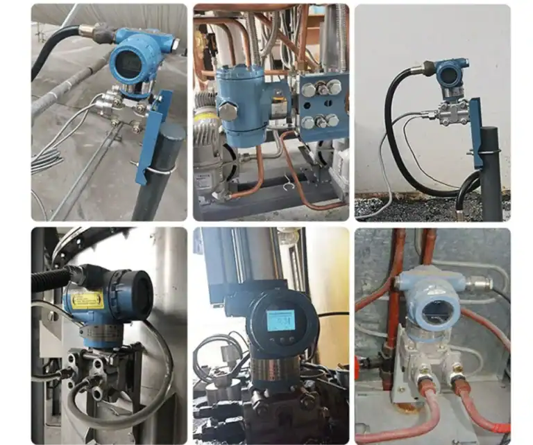
Best for: thermal oil heaters, industrial autoclaves, plastic-extruder barrel pressure, steam header monitoring, tank gas blanket pressure on hot vessels.
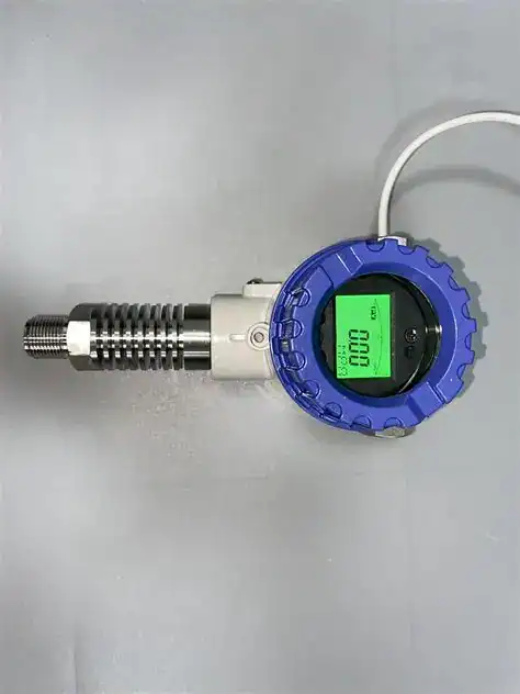
HMK’s standard product in this category is the HM80 High Temperature Pressure Transmitter — media temperature -40°F to +662°F (-40°C to +350°C), accuracy ±0.25% FS, zero-temperature coefficient ±0.03% FS/°C, range from -14.5 psi to 29,000 psi (-100 kPa to 200 MPa), 316L wetted parts, IP65/67. It uses a heat-pipe stand-off ahead of a diffused-silicon element. This is the right starting point for >90% of high-temperature applications under +662°F.
Method 2 — Direct High-Temperature Sensing Element (Up to ~+392°F / +200°C)
Instead of cooling the media, the sensor element itself is built from materials that handle heat directly. Two technologies dominate:
Ceramic capacitive (Al2O3). A thick-film alumina ceramic diaphragm flexes between two electrodes; capacitance change is read electronically. Ceramic has near-zero hysteresis, excellent corrosion resistance, and survives media up to about +257°F (+125°C) continuously. It is also the technology of choice for ATEX / intrinsically-safe installations because it has no fill fluid to fail.
Sapphire on titanium. A monocrystalline sapphire (Al2O3) sensing chip is bonded to a titanium isolation diaphragm. Sapphire’s thermal stability is exceptional — span drift can be held below ±0.015% FS/°C — and the assembly handles continuous service to +302°F (+150°C) with extended-range builds rated to +392°F (+200°C).
Strengths: compact, no stand-off needed, fast thermal response, often higher base accuracy than Method 1. Ceramic builds are ATEX-friendly. Sapphire delivers the lowest temperature drift of any common technology.
Trade-offs: more expensive than Method 1, narrower upper temperature ceiling (~+392°F / +200°C), and the maximum pressure range is generally lower than steel-diaphragm builds.
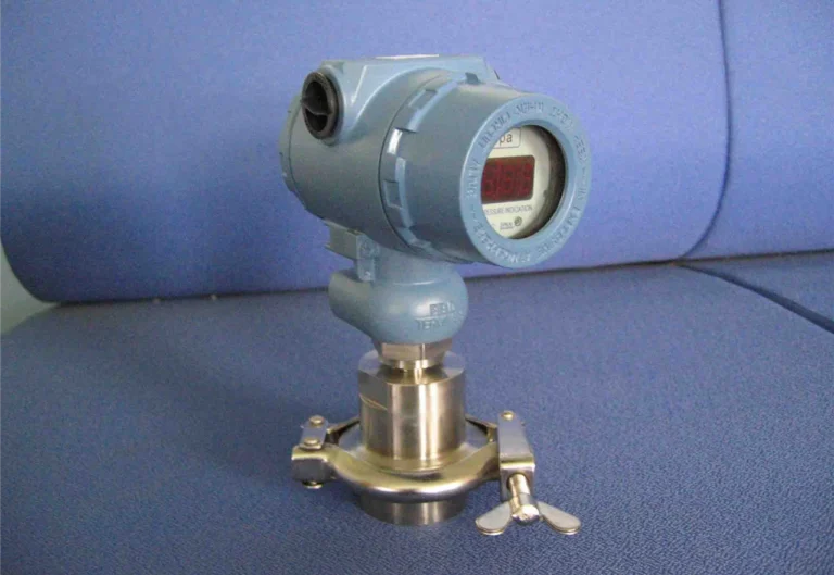
Best for: hydraulic systems with hot fluids, intrinsically-safe zones, food-grade or pharmaceutical autoclave service, applications where panel space rules out a stand-off.
HMK’s two products in this category:
- HM26 High Temperature Pressure Transmitter — ceramic capacitive Al2O3 element, media -40°F to +257°F (-40°C to +125°C), accuracy ±0.1 / ±0.25 / ±0.4% FS options, Ex ia II CT5 intrinsic safety certification, ranges to 14,500 psi (100 MPa).
- HM28 Sapphire Pressure Transmitter — sapphire chip on titanium diaphragm, media -85°F to +392°F (-65°C to +200°C) extended-range build, accuracy ±0.1% FS, span drift ±0.015% FS/°C, ranges to 37,700 psi (260 MPa).
If you need ATEX certification with a hot-but-not-extreme medium, choose HM26. If you need the lowest possible thermal drift across a wide working range, choose HM28.
Method 3 — Dynamic / High-Frequency Sensing (Up to ~+3632°F / +2000°C Transient)
This is a fundamentally different category. A piezoelectric or specially-mounted piezoresistive element is engineered for dynamic pressure — combustion pressure, blast waves, ballistic events, fast valve transients — where the measurement itself lasts microseconds. Because the heat exposure is brief, the sensor can survive media spikes far hotter than any continuous-duty transducer.
Strengths: rise times of ~1 μs, intrinsic frequencies into the MHz range, continuous service to +482°F (+250°C) and transient exposure to +3632°F (+2000°C). No fluid fill, robust against shock.
Trade-offs: measures change in pressure, not absolute static pressure. Charge-mode piezoelectric sensors need a charge amplifier and short cable runs. Cost per unit is several times Method 1.
Best for: internal combustion engine in-cylinder pressure, gas-turbine combustion diagnostics, rocket-motor static-fire tests, blast and shock-wave research, hydraulic pulsation analysis.
HMK’s product in this category is the HM90 Dynamic Pressure Transmitter. Standard build covers -40°F to +185°F (-40°C to +85°C); the high-temperature option (T2) extends continuous balancing service to +482°F (+250°C) and survives transient exposure to +3632°F (+2000°C). Intrinsic frequency 2 MHz, rise time 1 μs, accuracy ±0.1% FS.
If your application is static or slow-changing, do not use Method 3 — you will pay for bandwidth you cannot use and lose the static accuracy you actually need.
Method 4 — Isolation & Cooling Adapters (Up to +2192°F / +1200°C with Custom Builds)
When the process simply cannot be cooled, when the medium is corrosive or solidifying, or when the temperature exceeds what any direct sensor can take, the answer is to physically separate the sensor from the process. Two adapter strategies are common, and they can be combined.
Remote diaphragm seal with capillary. A thin metal isolation diaphragm contacts the process; a capillary tube filled with a high-temperature fill fluid (specialty silicone, halocarbon, or NaK alloy for the most extreme service) transmits pressure to a conventional transducer mounted in a cooler location. This is the standard solution for molten polymer, asphalt, slurries, and hot corrosive chemicals.
Water-cooled adapter. A jacketed mounting block with circulating cooling water (or refrigerant) sits between the hot process and a Method 1 or Method 2 transducer. The process side stays at full temperature; the transducer side is held at <+185°F (+85°C). For continuous service above +662°F (+350°C) — flue-gas systems, fluidized-bed boilers, glass-melting furnaces, metallurgical reactors — this is the only practical approach.
Strengths: no upper temperature limit set by the sensor itself — the limit is set by the diaphragm material and the fill fluid. Decouples sensor life from process severity. Water-cooled designs allow placement in radiant environments where ambient alone exceeds standard ratings.
Trade-offs: added installation complexity (cooling water supply, capillary protection), longer thermal response, and slightly degraded accuracy from the fill-fluid column.
HMK custom capability — up to +2192°F (+1200°C). Standard catalog products top out at +662°F (+350°C). For applications above this — coke-oven gas, copper-smelter off-gas, cement-kiln combustion zones, biomass-boiler superheaters — HMK builds custom water-cooled and remote-seal assemblies rated to +2192°F (+1200°C) continuous media temperature, with Inconel or Hastelloy diaphragms, NaK or proprietary high-temperature fill fluids, and 4-20 mA HART output to the cool-side transmitter. If your process is in this band and “off the shelf” doesn’t exist, this is what to ask for.
Method Selection Decision Matrix
The four methods overlap in the +250°F to +400°F band. Above and below that, the choice is clearer. The chart below maps each HMK product against its continuous-service temperature range, and the table that follows maps temperature bands to the recommended method and product.
| Process media temp | Measurement type | Best method | HMK standard product |
|---|---|---|---|
| up to +185°F (+85°C) | Static / slow | Standard transmitter (no high-temp design needed) | HM20 / HM30 family |
| +185°F to +257°F (+85 to +125°C) | Static, ATEX needed | Method 2 — ceramic | HM26 |
| +185°F to +392°F (+85 to +200°C) | Static, low drift critical | Method 2 — sapphire | HM28 |
| +257°F to +662°F (+125 to +350°C) | Static / slow | Method 1 — heat-pipe | HM80 |
| up to +482°F (+250°C) continuous | Dynamic / high-frequency | Method 3 | HM90 (T2 option) |
| +662°F to +2192°F (+350 to +1200°C) | Static | Method 4 — water-cooled / remote seal | HMK custom |
| Transient peaks to +3632°F (+2000°C) | Dynamic | Method 3 | HM90 (T2 option) |
Note that for static service, HMK’s standard catalog covers up to +662°F (+350°C) cleanly. The gap between +662°F and +2192°F is filled by custom water-cooled / isolated builds — these are not catalog items, so contact engineering with your media, pressure, and ambient conditions for a tailored quote.
Specs That Actually Matter for High Temperature Service
When you compare data sheets, four numbers separate a transducer that will hold up from one that will drift on you in six months.
Compensated temperature range. Don’t read the maximum media temperature first — read this. It tells you the band where the published accuracy is real. A transmitter that “handles 350°C” but compensates only to +85°C is, in practice, a low-temperature sensor with a heat-resistant front end.
Thermal zero shift and span shift, in % FS per °C. These are the two coefficients that govern drift across temperature. Anything above ±0.05% FS/°C will accumulate visible error across a 100°C temperature swing. The HM80 (±0.03% FS/°C zero coefficient) and HM28 (±0.015% FS/°C span drift) are at the better end of the industry; many low-cost units are 3–10× worse.
Wetted-material rating. 316L stainless is fine for clean steam, hot oil, and most general industrial fluids. For molten plastic, copper-bearing media, or chloride-rich condensate, specify Hastelloy C-276 or Tantalum. Sapphire and Al2O3 are excellent against aggressive acids but limit max pressure.
Seal material. Cross-check the O-ring or gasket spec against the actual continuous media temperature, not the peak. NBR ≤+212°F (+100°C), FKM ≤+392°F (+200°C), Kalrez ≤+617°F (+325°C), PTFE ≤+500°F (+260°C), all-metal seals above this.
A transducer that loses its seal at temperature will fail before its sensing element ever drifts.
Beyond the spec sheet, the underlying sensor element also drives long-term performance at elevated temperatures. Silicon-based piezoresistive elements and capacitive ceramic cells both have working limits and drift profiles that shift dramatically above +125 °C — a factor worth weighing before you finalize a platform. See how sensor-element choice under high-temperature stress plays out in the two dominant technologies.
Common Mistakes — and How to Avoid Them
Reading peak temperature instead of continuous temperature. A 1-second steam blow-down spike of +400°F is not a continuous +400°F service. The opposite is also true — never specify based on average if your process has predictable peaks above the rating.
Ignoring ambient temperature at the mounting location. A transducer rated for +662°F media installed inside a hot enclosure with +130°F ambient may overheat its electronics even with the stand-off doing its job. Always specify ambient separately from media.
Insulating the cooling fins. It happens more often than it should. The whole point of a Method 1 stand-off is convective heat dissipation; wrapping it in pipe insulation defeats the design and pushes heat into the electronics housing. Leave at least 4 inches of bare fin exposed.
Using a dynamic sensor for static measurement. A piezoelectric transducer measures pressure change. Its output decays under static pressure within seconds to minutes (unless integrated with a charge amplifier in long-time-constant mode). For tank pressure or steady-state line pressure, this is the wrong technology no matter how high its temperature rating.
Skipping the seal-material check. The element specs may be perfect, but if the catalog shipped the unit with NBR O-rings as default, your +250°F service will degrade the seal in months. Always confirm the seal material on the order, not just the model number.
Temperature is rarely the only stressor on the cell. On hot hydraulic and thermal-oil lines, fatigue from pressure cycling matters as much as the heat (see the hydraulic pressure transducer guide); where the sensor itself stays within rating but the reading still moves with ambient, that is sensor temperature compensation, not a high-temperature build. Two specialised models round out the steady-state options below: the HM28 sapphire-on-titanium sensor for class-leading drift to +392°F (+200°C), and the HM90 dynamic transducer with the T2 option for transient peaks.
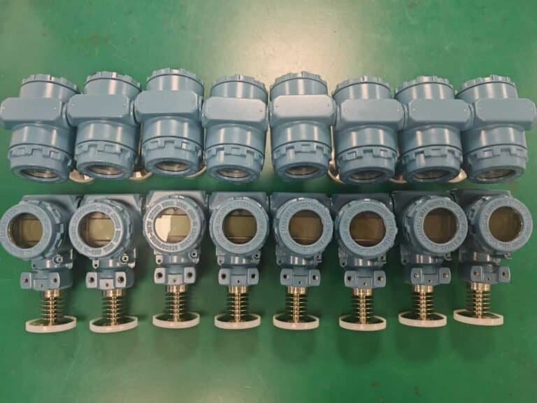
HM26 vs HM80 vs HM28: High-Temperature Model Comparison
The four methods above map onto HMK’s high-temperature line. The table compares the three direct-measurement models by sensing technology, temperature ceiling, accuracy, and the method each one fits.
| Model | Sensing technology | Max media temp | Accuracy | Range | Fits method |
|---|---|---|---|---|---|
| HM80 High-Temperature | Diffused-silicon piezoresistive, heat-pipe cooled | +350°C / +662°F (T1≤150, T2≤250, T3≤350°C) | ±0.25% FS | to 200 MPa | Method 1 – cooling stand-off |
| HM28 Sapphire | Sapphire element on titanium diaphragm | −65 to +200°C / +392°F | ±0.1% FS | to 260 MPa | Method 2 – direct element |
| HM26 High-Temperature | Ceramic capacitive (Al₂O₃) | +125°C standard, +350°C custom | ±0.1 / 0.25 / 0.4% FS | to 100 MPa | Method 2 – direct element |
Frequently Asked Questions
Is a pressure sensor for high temperature the same as a high temperature pressure transducer?
In purchasing language, yes. Engineers and catalogues use the terms interchangeably for any pressure measurement device engineered to survive media temperatures above the standard +185°F (+85°C) compensated range. A pressure sensor for high temperature service uses one of the four methods above: a heat-pipe stand-off for steady process up to +662°F (+350°C), a direct ceramic or sapphire element to +392°F (+200°C), a dynamic piezoelectric for combustion or blast events, or an isolating remote-seal / water-cooled adapter for service beyond +662°F. Pick the method by process temperature, dynamics, and media — the trade name on the data sheet is secondary.
Why does +185°F (+85°C) define a high temperature sensor?
+185°F (+85°C) is the upper bound on the compensated temperature range for most general-purpose silicon piezoresistive transmitters. Above this point the sensor element drifts predictably and the published accuracy spec no longer applies. ISA buyers and most industrial spec sheets treat any pressure sensor rated to hold accuracy above +185°F as a purpose-built high temperature design, which is why the four methods compared above exist.
What is the maximum temperature a pressure sensor for high temperature service can handle?
For continuous static service: heat-pipe stand-off designs reach +662°F (+350°C) off the shelf (HM80), sapphire-on-titanium extends to +392°F (+200°C) with class-leading drift (HM28), and water-cooled or remote-diaphragm-seal adapters reach +2192°F (+1200°C) as a custom build. For dynamic and transient service: piezoelectric sensors survive +3632°F (+2000°C) peaks while measuring microsecond pressure events (HM90 with T2 option). The sensor architecture matters more than the brand on the label.
Conclusion: Match the Method to the Process
There is no single “best” high temperature pressure transducer — only the right method for the temperature, the dynamics, and the media. As a quick recap:
- Up to +662°F (+350°C), static, general industrial: Method 1, heat-pipe stand-off — start with the HM80.
- Up to +257°F (+125°C), ATEX / intrinsic safety: Method 2, ceramic — the HM26.
- Up to +392°F (+200°C), low-drift critical: Method 2, sapphire — the HM28.
- Dynamic / combustion / blast, up to +3632°F (+2000°C) transient: Method 3 — the HM90 with T2 option.
- +662°F to +2192°F (+350 to +1200°C), static, extreme service: Method 4, water-cooled or remote diaphragm seal — HMK custom build, not a catalog item.
If you are working in the standard ranges, browse the full HMK pressure transmitter range and select directly. If your application is above +662°F continuous, or involves an unusual media or certification, send the process conditions (media, continuous and peak temperature, pressure range, ambient, mounting, certification) to the HMK engineering team — most extreme-service designs are quoted within two business days.
Picking the right method up front saves more in calibration drift and replacement cost than the price difference between any two of these transmitters.
Need a related comparison? If you are still deciding between sensor categories before getting to temperature, see Pressure Sensor vs Transducer vs Transmitter for the three-axis decision framework, or browse the full HMK pressure transmitter range to filter by application. If your service also involves vacuum, altitude, or a sealed closed system, our primer on absolute pressure vs gauge pressure walks through the reference-type decision.