Pressure Switch or Pressure Transmitter? A Decision Guide for Plant Engineers
A pressure switch trips a contact at a threshold. A pressure transmitter streams a continuous signal. Picking between them shapes your PLC wiring, your diagnostic options, and your panel BOM for the next ten years. This guide walks plant engineers through a five-criterion framework — control architecture, data value, safety integrity, integration cost, and lifecycle duty — and shows where hybrid electronic switches like the HM41 close the gap between the two.
The 30-Second Answer
The short version:
| What you need | What to specify |
|---|---|
| Binary on/off at a known threshold | Pressure switch (mechanical or electronic) |
| Continuous data, trending, SCADA variable | Pressure transmitter (4–20 mA / HART / RS485) |
| Both in one housing | Hybrid electronic switch such as HM41 |
| SIL-rated loop | Whichever model carries the certification your safety study demands — device class alone does not grant SIL |
If one row above already matches your loop, you have your answer. If the choice feels less clear — for instance your PLC has spare AI channels and the budget holder wants to know why you would pay for a transmitter — the five-criterion framework below makes the trade-off explicit.
What Each Device Actually Does (and Why “Switch vs Transmitter” Is Misleading)
A pressure switch turns a contact open or closed when pressure crosses a preset threshold. The output is a dry contact — normally open (NO) or normally closed (NC) — wired to a PLC digital input or directly into a motor starter. On the process side, the port is typically G 1/4 or 1/4 NPT — see NPT vs BSP/G thread comparison if your fleet mixes regions. On a P&ID, that contact is drawn next to a tag bubble labeled PSH or PSL — see the symbol convention guide. Inside the housing a diaphragm pushes against a calibrated spring until it snaps a microswitch. Electronic variants replace the spring with a solid-state sensor and programmable comparator, but the output type stays binary.
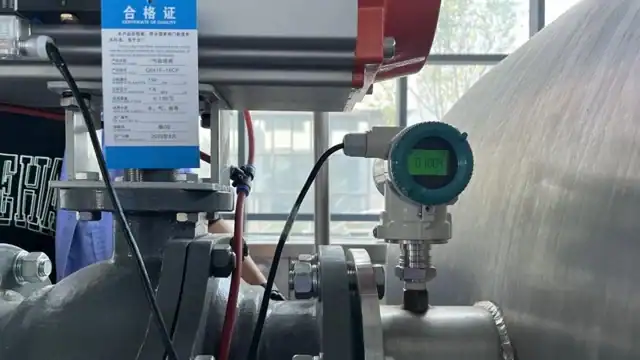
A pressure transmitter converts pressure into a proportional electrical signal. The most common output is a 4–20 mA current loop, with HART digital diagnostics layered on top in process industries and RS485 or voltage outputs available for simpler installations. The controller sees a continuous number that tracks pressure in real time — not just an edge event.
Two things have changed in the past decade that make the plain “switch vs transmitter” framing misleading for new specifications.
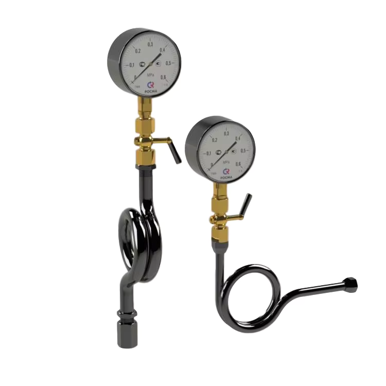
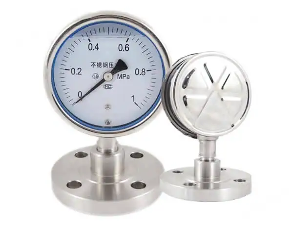
The first is accuracy architecture. Mechanical switches and gauges built around Bourdon tubes or diaphragm-and-spring assemblies typically land in the ±1 to ±2 percent full-scale range. Electronic devices — whether sold as switches or transmitters — commonly order at ±0.1 percent FS. Accuracy is no longer a switch-versus-transmitter question. It is a mechanical-versus-electronic one.
The second is the rise of hybrid electronic switches. Models like HMK’s HM41 combine dual SPDT relay contacts with a 4–20 mA analog output in one housing, which means a single instrument acts as both a switch and a transmitter. For deeper vocabulary around sensor, transducer, and transmitter, see our earlier breakdown at pressure sensor vs transducer vs transmitter.
The three-choice picture is how the rest of this article is structured. The next section turns the picture into a decision framework.
The Five-Criterion Decision Framework
Five questions settle the choice on almost every new pressure measurement point. Work through them in order.
1. Control architecture. Is the process controlled by a threshold or by a proportional loop? A pump that cycles between low and high levels, a compressor that trips on over-pressure, a filter that raises an alarm past a limit — these are threshold problems and a switch handles them directly. A PID loop modulating a control valve to hold 12.5 bar across varying demand is a proportional problem that requires the continuous signal only a transmitter provides. If you cannot name the proportional loop, you probably do not need one.
2. Data value. Will anyone use the pressure reading between threshold events? A maintenance team running condition-based work charts pressure trends to predict seal wear. An engineer troubleshooting a yield drop pulls last week’s pressure trace out of the SCADA historian. An audit file demands the process variable at one-minute resolution across the full batch record. Each of those needs a transmitter. A pure on/off interlock does not.
3. Safety integrity level. Does the loop fall under a SIL 1, 2, or 3 layer of protection? Both switches and transmitters exist in SIL-certified and uncertified variants. The safety study — FMEDA, proof test interval, proven-in-use data — decides which specific model qualifies, not the device class. Treat the SIL question as an orthogonal gate: pick any instrument that meets the other four criteria, then verify the specific model carries the certificate your safety case requires.
4. Integration cost. Does the PLC have a spare digital input or a spare analog input? Digital input cards cost less than analog input cards, but a transmitter’s HART diagnostics often pay back the hardware delta within the first instrument failure they prevent. Loop-powered 2-wire transmitters cut wiring to the same two conductors as a switch, eroding the old “switch is simpler to wire” argument. For the communication side of that trade-off, our HART vs 4–20 mA article walks through what the digital overlay actually buys you.
5. Lifecycle TCO. How long is the instrument expected to run, and what does a replacement cost the plant beyond the hardware? A mechanical switch in non-critical water service may run twenty years without attention. A mechanical switch on a reciprocating-compressor discharge cycling every ten seconds will fatigue its diaphragm long before the amortization schedule says replacement is due. Transmitters fail differently — typically electronic drift that calibration catches before it trips the loop — and tend to age more gracefully under cycling duty.
If four of the five answers point the same direction, that is the specification. When the answers split, the hybrid electronic switch covered later in this article often resolves the tie.
When a Pressure Switch Is the Right Answer
Five scenarios keep the pressure switch in the running despite everything the last section said about continuous data.
Simple pump cycling. A well pump, booster pump, or air compressor running between cut-in and cut-out pressures needs one decision per cycle: on or off. A pressure switch delivers that decision with no controller involvement at all. Installations like this have run unchanged in water utility packages for decades.
Threshold interlocks handled in PLC logic. When the PLC already compares values to setpoints — and most do — the cost difference between a DI channel and an AI channel matters at scale. On skid-based machines with dozens of pressure checks, switches on digital inputs keep the I/O architecture lean.
Power-independent fail-safe protection. Mechanical switches require no external power. The contact state reflects pressure even during a control-system failure, which is why they remain common in last-resort trip legs and fire-system pressure sensing.
Low-budget OEM equipment with a fixed setpoint. When the machine will never need reconfiguration, the simplicity of a factory-sealed switch outweighs the flexibility of a configurable device.
Independent SIS layers where the logic is simple. A SIL 1 or SIL 2 protection layer whose only function is “trip if pressure exceeds X” can often be built around a certified pressure switch more economically than around a certified transmitter plus a logic solver, provided the safety case accepts the switch’s failure modes.
HMK’s HM41 covers these scenarios while also providing an analog output if you later need the pressure value for trending or remote indication — a useful hedge when the machine specification has not fully frozen.
When a Pressure Transmitter Is the Right Answer
The transmitter becomes the default choice any time pressure turns into a variable rather than an event.
Process control loops. A PID loop modulating a valve or pump to hold pressure needs a proportional signal. The tighter the loop, the tighter the transmitter accuracy specification has to be. For how the sensor physics behind that accuracy actually works, our pressure transmitter working principle article walks through the bridge-and-diaphragm stack.
Predictive and condition-based maintenance. Trend-based maintenance depends on a continuous pressure record. Once you have the record, you can predict filter clogging, heat-exchanger fouling, or seal degradation weeks before an alarm would fire.
Multi-threshold requirements on a single tap. This is the scenario most SERP coverage misses: one transmitter plus PLC logic replaces several separate switches. A skid that needs low-low alarm, low alarm, high alarm, high-high trip, and an operational deadband around setpoint can handle all five thresholds from a single instrument. Wiring, enclosure space, and spare-parts stock all shrink. The trade-off is loss of the power-independent fail-safe contact — worth weighing, usually a favorable trade on modern plants with redundant control power.
Digital diagnostics. Models like HM25 and its peers support HART diagnostics that report loop health, sensor status, and secondary variables directly to asset-management software. The HART vs 4–20 mA piece covers the protocol trade-off in depth.
Regulated environments. Pharma CIP/SIP cycles, custody transfer in oil and gas, and food HACCP all require an audit trail of pressure versus time. Only a transmitter produces that record.
The Hybrid Zone: Modern Electronic Pressure Switches
A decade ago the choice was binary — mechanical switch or analog transmitter. Electronic pressure switches collapsed that binary. A single instrument now delivers relay output, 4–20 mA output, and often an RS485 link, all driven from the same solid-state sensor.
The practical effect is a three-option comparison:
| Device class | Output type | Accuracy grade | Setpoint adjustment |
|---|---|---|---|
| Mechanical pressure switch | Dry contact (NO/NC) only | ±1–2 % FS typical | Screw on the spring |
| HM41 hybrid electronic switch | Dual SPDT relay + 4–20 mA (RS485 optional) | Orderable at ±0.1, ±0.25, ±0.5, or ±1 % FS | Keypad, software-driven |
| Pure electronic transmitter | 4–20 mA / HART / RS485 | Typically ±0.1 % FS | Not applicable |
The HM41 is HMK’s in-house hybrid instrument line. Accuracy orders at four grades down to ±0.1 percent FS. Long-term stability stays inside ±0.2 percent FS in typical service. Overpressure tolerance is 1.5× the measurement range — 1.1× on the 100 MPa ranges — with sampling at 10 Hz. Dual SPDT relays rated 220 VAC / 24 VDC at 5 A handle the switching role; a 4–20 mA output is standard on every unit, with 0–5 VDC and RS485 as order-time options. The enclosure carries IP65 and operates from −10 to 70 °C.
The hybrid value shows up on the panel BOM. One HM41 replaces a mechanical switch plus a separate 4–20 mA transmitter on the same tap — saving one 2-wire loop run, two DIN-rail slots, and one calibration procedure every shutdown. The HM41 is not SIL-certified and does not support HART; loops with either as a hard requirement should pair a certified transmitter with a certified switch instead. The HM41 product page lists the complete order-code options.
Wiring Differences That Affect Your Panel Design
Wiring load drives a surprising amount of total cost on retrofit projects where cabinet space is already tight.
| Device | PLC card | Conductor count | Notes |
|---|---|---|---|
| Pressure switch | DI | 2 per channel | NO vs NC sets the fail-safe direction |
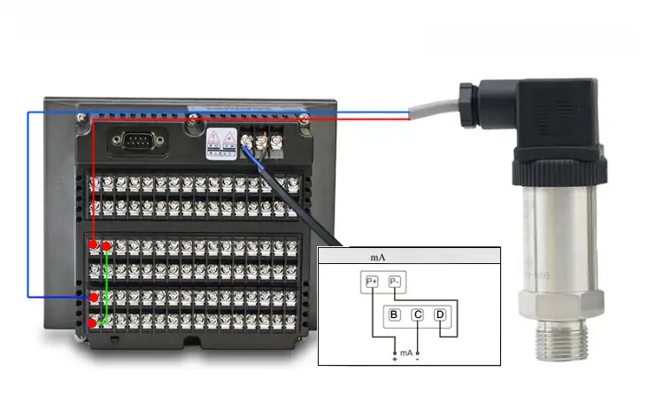
| Pressure transmitter | AI | 2 (loop-powered) or 3–4 (separate supply) | 2-wire matches a switch; extra conductors appear with local display or HART |
| Hybrid electronic switch | DI + AI | 4 wires minimum | Dual termination from one process tap |
The switch’s NO-versus-NC choice is a fail-safe decision: NC contacts open on loss of power, failing the protected function to a safe state; NO contacts close on energization and fail silent. Motor starters can drive directly from switch contacts with no PLC involvement.
Loop-powered 2-wire transmitters carry signal and supply on the same pair, so the wiring pulls match a switch one-for-one. See our 4–20 mA transmitter wiring guide for the loop topologies.
A hybrid switch uses one process tap but terminates on two different PLC cards — factor the doubled terminal count into your junction-box schedule before ordering enclosures.
Selection Guide by Industry
Industry-by-industry defaults give you a starting position before drilling into the five-criterion framework.
| Industry | Typical specification | Why |
|---|---|---|
| Compressed air · HVAC | Switch | Binary cut-in/cut-out usually sufficient |
| Water utility | Switch for pump control, transmitter for zone pressure monitoring | Distribution networks need trending |
| Oil and gas upstream · refining | Transmitter | SIS integration plus HART diagnostics on long loops |
| Chemical processing | Transmitter | Continuous monitoring of corrosion-prone loops |
| Pharmaceutical (CIP/SIP) | Transmitter | Regulatory audit trail of pressure vs. time |
| Food and beverage sanitary | Transmitter | HACCP and process-data requirements |
| Power generation | Transmitter on main steam; switch on auxiliary interlocks | Critical loops demand continuous signal; interlocks can be binary |
Two patterns run through the list. Industries regulated on the data itself — pharma, food, refining custody transfer — always pull toward transmitters because the audit file demands a continuous record. Industries regulated on the outcome — pump cycling, compressor tripping, fire protection — can still run on switches because only the event matters.
HMK’s pressure instrument catalog groups the HM20, HM25, and HM26 transmitter families alongside the HM41 hybrid switch so you can pick across the decision spectrum from a single supplier.
Field Failure Patterns We’ve Seen on Large Refinery Retrofits
In three decades of commissioning pressure instrumentation across Chinese refinery and petrochemical units, I have watched mechanical pressure switches fail in a predictable order.
Diaphragm fatigue leads the list — especially on interlocks tied to reciprocating compressors, booster pumps, or any cycling duty. Industry references put diaphragm life in the fifty-thousand to five-hundred-thousand cycle range, but the real number depends heavily on the medium, amplitude, and operating temperature. On hydrogen service I have pulled switches at thirty thousand cycles; on clean instrument air the same hardware has run past a million.
Contact arcing and pitting comes next, most often on inductive loads where the panel builder forgot the snubber.
Setpoint drift from spring relaxation shows up seasonally as ambient temperature swings.
Internal corrosion is the long-tail failure, appearing three to five years into service on H₂S or chloride-exposed loops.
The retrofit I see most often is a mechanical switch replaced with a hybrid electronic switch plus a separate transmitter. Over the three-year window after the swap, service calls on those points typically drop by a factor of two to three. The gains come mostly from eliminating the diaphragm fatigue and contact pitting modes; the transmitter’s diagnostic data catches setpoint drift long before it turns into an unplanned trip.
That pattern is why our team tends to specify transmitters wherever continuous monitoring value outweighs the simpler wiring of a binary switch.