Pressure Gauge Parts: 12 Components and What They Do
A mechanical pressure gauge looks simple from the outside (round dial, single needle, brass connection) but inside that case sit at least twelve cooperating parts, plus one optional thirteenth (the siphon coil) you only see in steam or hot-oil service. This guide walks each component, what it does, and which ones we see fail first on the maintenance bench. We end with the materials decision (wetted vs non-wetted), the four standards that actually govern these parts (ASME, EN, GB, JJG), and when it pays to leave the mechanical gauge behind for a digital readout.
Worth knowing: the same temperature that warps a Bourdon tube also pulls electronic transmitter readings off-spec. We unpack the maths in pressure sensor temperature compensation, how it works, including a worked example for the +/- %FS/°C number on every datasheet.
What a Pressure Gauge Actually Does
A pressure gauge is a mechanical instrument that converts process pressure into a needle position you can read at a glance. Liquid or gas pressure pushes against an elastic sensing element (most commonly a curved Bourdon tube) and the tiny deflection of that element is amplified by a movement train into a 270° pointer sweep across a calibrated dial.
Nothing on the outside tells you which sensing element is inside, what alloy the wetted parts are, or whether the case is filled with glycerin. To spec one, troubleshoot one, or know what to replace when it drifts, you need the parts list. Once you can name the parts, reading the dial correctly becomes second nature.
The 12 Parts of a Pressure Gauge — Plus 1 Optional
We list the parts in process-flow order: media enters at part 1, pointer-on-dial is the user-visible end at part 12. The thirteenth (siphon coil) is optional but mandatory in steam or hot-oil service; it sits between the pipeline and the gauge socket.
- Process connection (socket / inlet), the threaded fitting that screws into your pipe. Common standards: ¼″ NPT, ½″ NPT, G¼, G½, M20×1.5. The threads matter, see NPT vs G thread selection before you order replacements.
- Restrictor / snubber orifice, a tiny pinhole, typically 0.3–0.6 mm, machined into the socket bore or fitted as a screw-in insert. It dampens pulsation and protects the Bourdon tube from particulate. Top-end gauges always have one; budget gauges leave the socket bore wide open.
- Bourdon tube, the C-shaped, helical, or spiral hollow tube that flexes when pressurised. The flat-oval cross-section tries to round out under pressure, which uncoils the tube (WIKA’s principle write-up is a good visual primer). Material choices include phosphor bronze, 316 stainless, Monel 400, and Inconel X-750. The tube alone determines the pressure range and the corrosion envelope.
- Linkage, a small adjustable arm pinned to the free end of the Bourdon tube. Length and pivot location set the calibration span; technicians use it to fine-tune the gauge after a recalibration.
- Pinion + sector gear (the “movement”), a precision toothed pair that converts the few millimetres of Bourdon tip travel into ~270° of pointer rotation. Brass on brass for general service, hardened on hardened for high-cycle hydraulic.
- Hairspring, a thin spiral spring around the pinion shaft. It removes mechanical backlash so the pointer reads the same on rising and falling pressure, not 1–2 % FS apart. A worn or unhooked hairspring is the single most common reason for “loose pointer.”
- Pointer (needle), the visible indicator. Press-fit on the pinion shaft. Pointer drift is usually a hairspring problem, not a pointer problem.
- Dial face, the printed scale, almost always 270° spread. Black-on-white aluminium for general service; white-on-black or photoluminescent for outdoor / low-light. Customisable for psi, bar, kPa, MPa, or dual-scale.
- Window, the transparent cover. Plain glass for cheap commercial; safety glass, acrylic, or polycarbonate for impact-rated; polysulfone for high-temperature steam-line work.
- Bezel ring, the metal ring that clamps the window onto the case. Three styles: friction (snap-fit), threaded screw-on, or bayonet quarter-turn for tool-free service.
- Case, the housing that protects everything inside. Material is usually ABS, painted steel, 304 stainless, or 316 stainless. Geometry comes in two grades that matter (see H2-5).
- Internal fill (glycerin or silicone), optional, but mandatory in pulsating service. Fills the case 95–98 % to damp the pointer in vibration, lubricate the movement, and stop condensation inside the window. Silicone for low-temperature (−40 °C and below); glycerin for everything else.
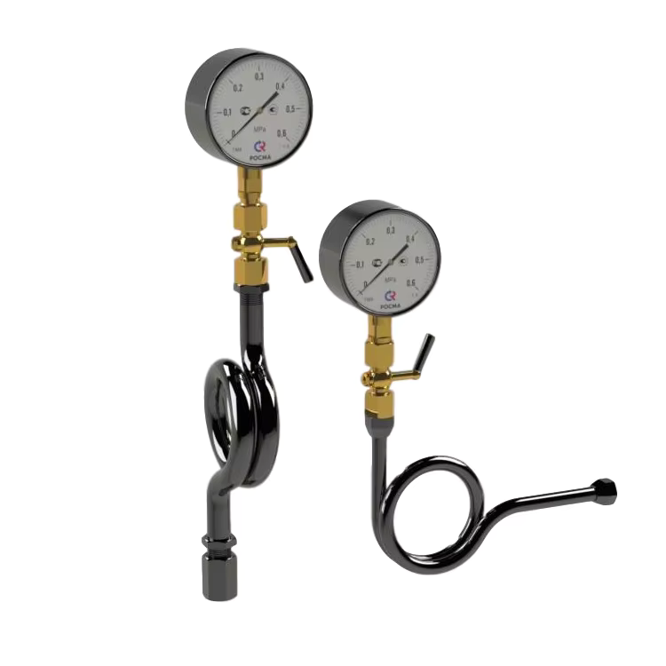
- Optional: Siphon coil / pigtail / impulse line, a U-shape, pigtail, or coiled tube installed between the pipeline and part 1. It traps a column of condensate, so live steam never reaches the Bourdon tube. Without it a 250 °C steam line cooks the gauge in days.
Signal Path: From Process Media to Pointer
The twelve parts cooperate in a six-step chain, sketched in the cross-section below.
- Media enters the socket, passes the restrictor, and reaches the closed end of the Bourdon tube.
- Internal pressure tries to round the flat-oval cross-section, which makes the tube uncoil. Free-end displacement is small, typically 3–7 mm at full scale on a C-tube.
- The linkage transfers that linear motion to the input arm of the sector gear.
- The sector gear meshes with the pinion at a roughly 50:1 ratio, multiplying the small linear displacement into a 270° rotation.
- The pointer, press-fitted to the pinion shaft, sweeps the dial.
- The hairspring, hooked to the pinion, stays in slight tension across the whole travel; that is what eliminates the “rising-vs-falling” hysteresis an unsprung mechanism would show.
When a mechanical part wears past its tolerance (sector tooth backlash, hairspring fatigue, or linkage slack), accuracy collapses faster than it does in a piezoresistive or capacitive sensor, where the equivalent of “wear” is decade-scale long-term drift.
Wetted vs Non-Wetted Parts: Why Material Matters
Inside the gauge, only three parts touch the process fluid: the socket, the Bourdon tube, and (when fitted) the restrictor. Together these are the wetted parts. Everything else (window, bezel, case, dial, movement) never sees the process and has to survive the ambient environment only (humidity, splash-down, vibration, temperature).
Material selection for wetted parts follows four rules from refinery and water-treatment practice. China’s SH/T 3092-2008 Code for Instrument Selection in Petrochemical Engineering codifies these clearly, and the same logic applies on a Mumbai refinery FCC unit or a Gulf-state desalination plant.
| Service | Wetted-parts material | Why | Avoid |
|---|---|---|---|
| Mild service: clean water, air, hydraulic oil, mild lubricants | 316 / 316L stainless | Inexpensive, weldable, atmosphere-resistant | Plain carbon steel for outdoor use |
| Sour service: wet H2S above trace | Monel 400 or Hastelloy C-276 | Sulphide cracking immunity (SH/T 3092 sour-service clause) | 304 / 316 austenitic stainless |
| High-cycle hydraulic ≥ 500 bar | Inconel X-750 | Fatigue resistance under reversal | 316 SS Bourdon tube |
| Halide service: chlorides, fluorides, brackish water | Hastelloy C-276 or duplex stainless | No pitting, no SCC | 316 (pitted within months) |
| Oxygen service | 316L cleaned to ASTM G93 Level C | No hydrocarbon ignition source | Phosphor bronze |
The non-wetted parts pick up the ambient problem set: 304 case for indoor or sheltered outdoor, 316 case for offshore / coastal salt-spray, and acrylic windows where impact-resistance matters more than scratch-resistance.
Case Construction: Open-Front, Solid-Front, Liquid-Filled
The case (part 11) is not a single thing, it is one of three constructions, picked from your operating pressure and personnel-safety risk.
| Case grade | Front | Back | Typical use | Pressure ceiling |
|---|---|---|---|---|
| Type I, Open-front | No partition between Bourdon tube and window | Plain or vented | Indoor commercial, low pressure | < 60 bar / 1000 psi |
| Type II, Solid-front + blowout back | Steel partition behind dial; pressure relief panel on the back | Pressure-relief plug | Process plant, industrial hydraulics | up to 700 bar / 10,000 psi |
| Type III, Liquid-filled | Either I or II, glycerin or silicone fill | Diaphragm or vent plug for thermal expansion | High-vibration, pulsating service, safety-critical | matches the underlying I or II |
ASME B40.100-2013 codes Type II as the safe choice when burst-failure of the Bourdon tube could send fragments at the operator. Liquid-fill (Type III) is the standard fix for vibration on reciprocating-pump skids and oil-rig applications.
Standards That Govern Each Part
Four written standards govern construction, accuracy, and verification of mechanical pressure gauges. Engineers writing specs for global plants pick the right one for the project’s home jurisdiction.
| Standard | Region | What it covers | Accuracy classes |
|---|---|---|---|
| ASME B40.100-2013 | US / North America | Case grades, accuracy grades, pressure-element materials, cleaning for oxygen service | Grade 4A (0.1 %) / 3A (0.25 %) / 2A (0.5 %) / A (1 %) / B (2 %) / D (5 %) |
| EN 837-1:1996 | EU / global OEM | Bourdon-tube gauge construction, accuracy, dimensions | Class 0.1 / 0.25 / 0.6 / 1.0 / 1.6 / 2.5 / 4.0 |
| GB/T 1226-2017 | China / SE Asia OEMs | General-purpose dial pressure gauges; tolerance budget per part | Class 0.4 / 1.0 / 1.6 / 2.5 / 4.0 |
| JJG 52-2013 | China metrology | Periodic verification: 6-month / 1-year recalibration cycles, mechanical wear judgement criteria | Same classes as GB/T 1226 |
The classes line up across the standards within ~20 %. A “Class 1.6” gauge under GB/T 1226 is roughly equivalent to a “Grade A” gauge under ASME B40.100, both call for ±1.6 % FS at mid-scale and ±2.5 % FS at the extremes. JJG 52 is the only one that prescribes how often you have to verify the gauge in service, which is what a maintenance team actually cares about. Verification chains back to a national pressure-metrology lab, in the US, NIST’s pressure and vacuum group anchors the traceability for everything in this table.
Wear Patterns and Replaceable Parts
Some parts inside the gauge are designed to be replaced. Others are replace-the-whole-gauge calls. Knowing which is which saves a lot of unnecessary teardown.
Replaceable in the field, no special tools:
- Window (when cracked or hazed)
- Bezel ring (snap-on or bayonet, friction bezels need a press)
- Pointer (after a calibration overshoot)
- Glycerin fill (after thermal expansion has pushed it out the vent)
- Dial face (for relabelling, usually a re-certification job)
Replaceable on the bench, with the right movement-puller:
- Movement assembly (sector gear + pinion)
- Hairspring (almost always together with the movement)
- Linkage (usually replaced as part of the movement kit)
Throw away the whole gauge:
- Bourdon tube fatigue cracks (visible as a hairline at the inner radius of the C)
- Socket corrosion or thread damage
- Case dent that has reached the movement well
- Solid-front partition failure
In Asian refinery and cement-plant maintenance reports we see across HMK customers, the typical wear order on a Class 1.6 industrial gauge in pulsating service follows this sequence:
| First failure mode | Typical onset | Symptom you see on the dial | Field fix |
|---|---|---|---|
| Hairspring fatigue / un-hook | around 6 months | Pointer “loose”, different reading rising vs falling | Bench replacement of movement |
| Sector-gear backlash | around 18 months | Pointer jumps in 1–2 % FS steps | Movement kit swap |
| Glycerin-fill yellowing | around 36 months | Window hazes, dial hard to read | Drain, refill, replace window |
| Bourdon-tube fatigue crack | 5–10 years (clean) / 1–3 years (pulsating) | Reads zero or stuck at full scale | Replace whole gauge |
Indian fertiliser plants and Philippine geothermal sites report the same sequence; the wear is mechanical, not climatic. JJG 52-2013 sets the recalibration trigger at whichever comes first between the published cycle and a 1.6 % FS reading drift, based on HMK customer field reports across multiple Asian refinery and cement sites.
When the parts you need are in the “field” or “bench” rows above, distributors like Crane Engineering, Ashcroft, and WIKA stock OEM-spec replacement bezels, windows, and movement kits keyed to gauge model number, order against the gauge’s existing tag, not against generic part numbers.
When Mechanical Parts Aren’t Enough: The Digital Alternative
A mechanical gauge tops out at Class 0.1 (≈0.1 % FS) under EN 837-1, and that class is rare and expensive, most industrial mechanical gauges sit at Class 1.6 (1.6 % FS). When the application asks for any of the items in the right column, the mechanical answer breaks down:
| Capability | Mechanical Bourdon gauge | Digital pressure gauge (HM40) |
|---|---|---|
| Best practical accuracy | Class 1.6 typical / 0.4 attainable | ±0.1 % FS selectable |
| Output signal | None, visual only | 4–20 mA, RS-485, optional |
| Data logging / SCADA | No | Yes via 4–20 mA / Modbus-RTU |
| Vibration tolerance | Fails at <2 g without liquid fill | Solid-state, no movement to wear |
| Power | None | Battery (24-month) or 24 VDC / 220 VAC |
| Display in low light | Mechanical luminous dial | Backlit LCD/LED |
| Recalibration cycle | 6–12 months (JJG 52) | 12–24 months typical |
The drop-in replacement keeps the same socket size and thread, swaps the mechanical guts for a pressure transducer + 4-digit display, and adds an electrical output. The HMK HM40 Digital Pressure Gauge is built for this swap: ±0.1 % / 0.25 % / 0.5 % FS selectable accuracy, 0–100 kPa to 0–100 MPa range, 316SS wetted parts, IP65, dual 4-digit LCD, and either battery (24-month life) or 24 VDC / 220 VAC mains. With the optional 4–20 mA or RS-485 output, the same instrument bridges into a SCADA or PLC loop. We’ve written the full mechanical-to-digital decision in the electric oil pressure gauge guide. If an output signal is the primary requirement and the dial is incidental, look at the HM23 HVAC/R compressor pressure transmitter or browse the full pressure transmitter types pillar.
FAQ
What are the components of a pressure gauge?
Twelve parts in process-flow order: socket, restrictor, Bourdon tube, linkage, pinion + sector gear, hairspring, pointer, dial, window, bezel, case, and (often) liquid fill. A thirteenth (a siphon coil) is added between pipeline and gauge in steam or hot-oil service.
What is the lifespan of a pressure gauge, and how often does it need to be replaced?
A liquid-filled Class 1.6 industrial gauge in clean service lasts five to ten years before mechanical drift exceeds tolerance. In pulsating, vibrating, or high-temperature duty that drops to one to three years. JJG 52-2013 sets the verification cycle at six months for safety-critical service and one year for general process service, verification, not necessarily replacement. A gauge that fails verification by less than its tolerance class can usually be recalibrated; one that drifts further than its class needs the movement replaced or the whole gauge swapped.
What is the purpose of a siphon tube on a pressure gauge?
A siphon tube (also called a pigtail or impulse line) holds a permanent column of cooled condensate between a hot-fluid pipeline (most commonly live steam) and the gauge socket. The column physically isolates the Bourdon tube from temperatures that would anneal its alloy. Without it, a 250 °C steam line will cook a 316SS Bourdon tube within days; with one, the gauge sees something close to ambient.
What materials are wetted parts in a pressure gauge made of?
The default is 316 / 316L stainless steel for the socket, restrictor, and Bourdon tube. For sour service (H2S), Monel 400 or Hastelloy C-276 replace the stainless. For halide service (chlorides), Hastelloy C-276 or duplex stainless are the only sound choices, austenitic 316 fails by pitting. For high-cycle hydraulic above 500 bar, Inconel X-750 resists fatigue cracking that ordinary stainless does not.
Can pressure gauge parts be replaced in the field?
Yes for the externals and the fill: window, bezel, pointer, and glycerin can be swapped on the line. Movement parts (sector gear, hairspring, linkage) require a bench, a movement-puller, and a recalibration step. The Bourdon tube and socket are not field-replaceable; corrosion, fatigue, or thread damage on either of those means a whole-gauge replacement.
Looking to replace a worn mechanical gauge with a digital readout? See the HM40 Electronic Pressure Gauge, same socket size, ±0.1 % FS, 24-month battery option, no movement to wear out.
Related reading: These parts behave differently in different industries. See the industry-by-industry application guide for which combinations actually survive in service. When the gauge sits upstream of a regulator on an air or hydraulic main, see Supply Pressure Gauge: What It Does and Where to Spec It for the psi range each application expects.
The accuracy class number on the dial (Cl 1.6, Cl 1.0, etc.) is the maximum allowed error as a percent of full scale. For the complete 9-grade ladder and how to choose the right class for your application, see Pressure Gauge Accuracy Class.