Electric Oil Pressure Gauge: Mechanical vs Sender-Driven vs Digital LCD
An electric oil pressure gauge converts oil-line pressure into an electrical signal: a resistive sender driving a needle, or a 4-20 mA transmitter feeding an LCD or DCS, so the oil itself never leaves the engine room. This guide is for the engineer asked to spec or replace an oil pressure gauge on a pump, compressor, hydraulic power pack, or lube oil console. If you are wiring an aftermarket gauge into a classic car or motorcycle, AutoMeter and GlowShift cover that ground better than we will. Picking between mechanical, sender-driven electric, and digital LCD is not “which is most accurate”; it is a product of remote-readout need, DCS interlock, accuracy class, and EMI environment.
The accuracy advantage of an electronic gauge depends on how well it suppresses thermal drift. See pressure sensor temperature compensation for the maths behind the +/- %FS/°C spec, plus the passive and active circuits that produce it.
A mechanical gauge has 12 internal parts, each of which can drift, wear, or fail in the field. The digital alternative replaces all of them with a transducer plus a 4-digit display.
The Three Types at a Glance
In an industrial lube loop, “electric oil pressure gauge” usually means one of three devices, and they are not interchangeable.
| Type | How it reads | Typical accuracy | Where it fits |
|---|---|---|---|
| Mechanical Bourdon (often liquid-filled) | C-tube deflects a needle on the gauge body | Class 1.6 (±1.6% FS) per GB/T 1226 | Local indication on pump skid, no remote readout |
| Sender-driven electric | Resistive sender (240→33 Ω) drives an air-core movement on a remote dial | ±5% FS | Legacy aftermarket and small OEM panels with one or two gauges |
| Digital LCD / 4-20 mA | Pressure transducer + LCD readout, optional 4-20 mA / RS485 / HART | ±0.1% to ±0.5% FS | DCS-integrated lube monitoring on critical rotating equipment |
The word “electric” is the source of most spec-sheet confusion. In refinery and plant practice it does not automatically mean a 4-20 mA loop. It includes both the resistive sender legacy (rooted in automotive design) and the modern digital transmitter family. The rest of this guide separates the two.
Industrial vs Aftermarket: Where the Spec Fork Lives
The cheap “electric oil pressure gauge” sold at AutoZone or AutoMeter is a 12 V single-wire device built for a dashboard. The instrumentation we ship to a pump skid in a refinery is a 24 VDC two-wire device built for a marshalling cabinet. The differences are not cosmetic.
| Spec | Aftermarket dashboard gauge | Industrial 4-20 mA gauge |
|---|---|---|
| Power | 12 V common-ground | 24 VDC isolated loop |
| Signal | Variable resistance to ground | 4-20 mA (or HART overlay) |
| Accuracy | ±5% FS | ±0.1% to ±0.5% FS |
| EMI immunity | None specified | IEC 61000-4 level 3 or higher |
| Standard | SAE J1810 family | IEC 60770-1, GB/T 1226, JJG 52 |
Sinopec design rules for refineries (per the SH/T 3092 design specification family) require oil pressure on critical pumps and compressors to have both a local indicator and a remote transmitter feeding the DCS. The DCS interlock trip on a turbine lube oil header is commonly set near 0.05 MPa low. A single-point cable failure on a 12 V automotive sender would not survive that audit.
If your application is the dashboard of a passenger vehicle, the sender-driven section below will help. If it is a plant lube oil header, jump straight to the digital LCD section and the wiring write-up that follows.
How a Sender-Driven Electric Gauge Works
A sender-driven gauge uses a 1/8″ NPT sender threaded into the oil port. Inside, a wiper rides a curved resistance blade; rising pressure pushes the wiper toward the low-resistance end. A common automotive curve is 240 Ω at 0 psi, ~103 Ω at half scale, ~33 Ω at full scale. The dash gauge is essentially an ammeter; current rises as resistance falls, and an air-core movement deflects the needle.
The failure habit is the trap. When the sender wire shorts to ground, current goes up, not down, and the needle pegs full instead of zero. If the gauge reads pegged with a healthy engine, suspect the sender or its wire before the gauge head. A multimeter across the sender terminal at zero pressure should read close to 240 Ω.
Tolerance is ±5% FS at best. For a one-dial skid that is fine. For DCS integration it is not.
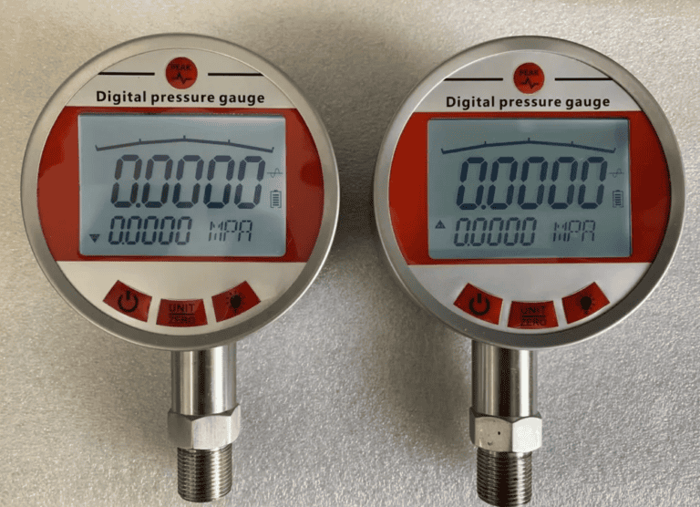
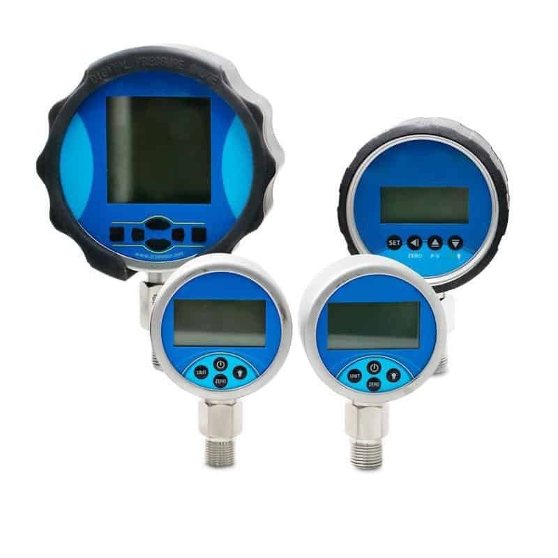
How a Digital LCD Gauge Works (HM40 as Reference)
A digital electric oil pressure gauge replaces both the sender and the air-core movement with a transducer, an analog-to-digital converter (ADC), a microcontroller, and an LCD. The HMK HM40, co-developed with German HELM sensing elements, is a working reference.
Verified live specs:
- Range: vacuum (-100 kPa) to 100 MPa gauge
- Accuracy: ±0.1% FS, with selectable ±0.1% / ±0.25% / ±0.5% classes
- Long-term stability: ±0.2% FS per year
- Display: 4-digit LCD on battery models, 4-digit LED on mains models
- Sampling rate: 5 Hz with built-in peak-value capture
- Optional signal: 4-20 mA, 0-5 VDC, or RS485 alongside the local readout
- Power: battery (up to 24 months), 24 VDC, 220 VAC, or 380 VAC
- Protection: IP65, 316 stainless wetted parts, -10 °C to +70 °C operation
Where the cost lives is not the LCD. It is the temperature compensation, the ADC, the loop isolation, and the EMI filtering. These are the parts that make a ±0.1% reading stay ±0.1% after a year on a steam-flange-adjacent pump skid. The accuracy gap between a sender-driven dash gauge (±5% FS) and an HM40 (±0.1% FS) is roughly fifty-fold.
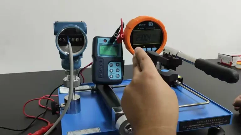
Accuracy and Calibration: GB/T 1226 vs ASME B40.100
The Chinese national standard GB/T 1226-2017 (General Pressure Gauges) defines four accuracy classes: 1.0, 1.6, 2.5, and 4.0, corresponding to ±1%, ±1.6%, ±2.5%, and ±4% FS. The reason the series jumps from 1.0 to 1.6 instead of 1.5 is the R5 preferred-number rule: the common ratio 10^(1/5) ≈ 1.6 is the standard rounding step for international tolerance series, and 1.5 simply does not belong to it.
The U.S. equivalent ASME B40.100 uses letter grades. The mapping engineers actually use:
| GB/T 1226 class | Tolerance | ASME B40.100 grade | Notes |
|---|---|---|---|
| 1.0 | ±1.0% FS | Grade A | Process indication |
| 1.6 | ±1.6% FS | Grade B | Plant standard |
| 2.5 | ±2.5% FS | Grade C/D | Utility / non-critical |
| — | ±0.5% FS | Grade 2A | DCS feedback class |
| — | ±0.1% FS | Grade 4A | Calibration laboratory |
In China, JJG 52 (the verification regulation for elastic-element pressure gauges) sets verification intervals at six months or less for in-service instruments. Plant transmitter performance is also bounded by IEC 60770-1 (industrial-process measurement transmitters, performance evaluation). One trap to avoid: the LCD “display resolution” on a digital gauge is not the system accuracy. A four-digit LCD can display 0.05% steps and still carry a ±0.5% FS class. Always read the accuracy line on the datasheet, not the digit count.
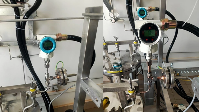
Wiring: Three Loops Drawn Out
There are three loops you will see in the field, and they do not share connectors.
Single-wire automotive sender (240→33 Ω). A single conductor leaves the sender, picks up 12 V through the gauge, and grounds through the engine block. EMI immunity is whatever the wiring run happens to provide, usually nothing.
Two-wire 4-20 mA transmitter. Two conductors run from the marshalling cabinet to the transmitter. One carries 24 VDC out, the other returns 4-20 mA proportional to pressure. The loop is isolated from earth at the cabinet, which is what gives the transmitter its EMI rating.
HART overlay on 4-20 mA. The same two wires carry both the analog current loop and a digital signal at the FSK (frequency-shift keying) band (HART specifications via FieldComm Group). A HART-aware host (DCS card or handheld communicator) can read range, units, and diagnostics without breaking the loop.
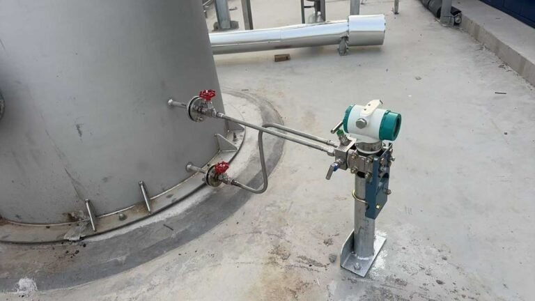
Plant practice on the mechanical side is to leave a take-off port and a vent valve upstream of any electric instrument so it can be isolated and replaced without draining the lube system.
Common Failure Modes That Get Misdiagnosed
Of the field calls we get on lube-oil pressure indication, the head unit itself is rarely the fault. The five things that actually fail:
- The sender drifts or shorts; the dash reads pegged.
- A ground loop on the marshalling cabinet shifts the apparent zero on a 4-20 mA loop.
- Vibration on a rotating-equipment skid breaks the sender lead at its crimp.
- Water in the oil corrodes the sender face and the readout looks erratic.
- The DCS filter time is set too long, so the indicated pressure lags the real event by seconds, and operators chase ghosts.
One example from a Chinese refinery atmospheric distillation feed pump: the original mechanical class 1.6 gauge on the seal-flush oil header lagged transients by two to three seconds, masking real events. After a swap to a 0.5% FS digital gauge with 4-20 mA into the DCS interlock, seal failures on that line dropped from four in the prior period to zero over the following six months. The gauge itself was not the fix. The loop bandwidth and the interlock were.
First move on any “the gauge is broken” call: ohm out the sender. Nine times in ten the head is fine.
Spec-Sheet Decision: 5 Questions to Pick the Right Type
Walk these in order. The answers route to one of three paths.
- Need a remote readout? If no, a liquid-filled mechanical Bourdon is the cheapest correct answer.
- Tied into DCS or PLC interlock? If yes, 4-20 mA digital is mandatory. A 240 Ω sender will not pass the audit.
- Accuracy class? ±1.6% FS for indication, ±0.5% FS for DCS feedback, ±0.1% FS for cal-lab.
- EMI environment? Near VFDs or large motors → IEC 61000-4 level 3 is the floor.
- Calibration drift sensitive? Lean digital with a stable sensing element over a 240 Ω air-core combination.
For most plant work the answer is path C: a digital 4-20 mA instrument like the HM40, feeding the DCS while showing a local readout. For deeper background, see our pressure transmitter types pillar.
FAQ
Is an electric oil pressure gauge more accurate than a mechanical one?
It depends on the type. A digital instrument at ±0.1% to ±0.5% FS is tighter than a mechanical class 1.6 gauge (±1.6%); a 240 Ω sender-driven dash gauge at ±5% FS is looser than both.
Can I replace a mechanical Bourdon gauge with an electric one without changing the port?
Sometimes. Aftermarket senders are 1/8″ NPT; industrial transmitters are usually G1/4 or 1/2″ NPT. Check thread and seal first (NPT vs G thread guide).
How long does an electric oil pressure gauge last?
Battery-powered digital instruments like the HM40 run about 24 months per battery; the sensing element lasts far longer. Senders typically last five to ten years before drift.
What’s the difference between a 240 Ω sender and a 4-20 mA transmitter?
The first is a passive resistor on a single-wire loop; the second is an active two-wire current loop with isolated power and much higher EMI immunity.
Why does my electric gauge read full when the engine is off?
Almost always a shorted sender or a sender wire grounded against chassis. Ohm the sender; it should read close to its zero-pressure value (240 Ω on automotive parts).
Related field guide: when the dial actually starts to dance during a shift, work through Oil Pressure Gauge Fluctuating: 5 Causes and Field Fixes — the five-cause decision tree separates a wiring or transmitter fault from a real oil-system problem in under five minutes. For the upstream side of the same loop, see Supply Pressure Gauge: What It Does and Where to Spec It — the spec-engineer’s reference for psi ranges and P&ID symbol.
Intake-manifold vacuum (-0.5 to -0.7 bar at idle) and brake-booster vacuum show up as negative readings on the gauge. For the cross-domain picture — automotive intake, HVAC duct, cleanroom, refrigeration suction, boiler draft — see Negative Pressure Gauge Applications.
Next step: Send your spec sheet for a model recommendation in 24 h. Get in touch →