Pressure Switch Symbol Guide: Electrical Schematics, P&ID & Pneumatic Standards

You opened a drawing, found a circle or a contact tagged “PSH-201”, and the legend page is missing. This guide walks through the pressure switch symbols you meet on three drawing standards: electrical schematics, P&IDs, and pneumatic-hydraulic circuits. It also clears up the NEMA-versus-IEC mismatch that trips up multinational EPC projects.
One Switch, Three Symbols — Why Drawings Disagree
A single industrial pressure switch (bellows, diaphragm, or piezoresistive sensor wired to a snap contact) shows up as three different glyphs depending on the drawing:
- Electrical schematic (motor control, HVAC wiring, EPLAN exports): a normally-open or normally-closed contact with a pressure-actuator hint. Standards: IEC 60617-7, NEMA, JIC NFPA T3.7.1.
- P&ID (process flow, EPC blueprints): an instrument bubble. A circle with a tag like PSH or PSL. Standard: ANSI/ISA-5.1-2024.
- Pneumatic or hydraulic circuit (compressor controls, brake systems): a function block. A square envelope with port labels. Standard: ISO 1219.
Disambiguation. This article covers industrial pressure switches used in process and machine control. It does not cover the I/O button on consumer electronics, and it does not cover residential well-pump pressure switches (the cylindrical contactor on a pump tank). Different devices, different drawings, different symbols.
Electrical Schematic Symbol — NO / NC / SPDT Contacts
If you only ever read one pressure switch symbol, this is the one. On an electrical schematic, a pressure switch is a contact (NO or NC) connected to a pressure-actuator hint, typically a half-circle or bellows with an arrow that tells you whether rising or falling pressure trips the contact. Symbols are drawn in their unpressurized, de-energized state. What you see on paper is the rest position.
Anatomy
A complete symbol has three parts. The contact is two short horizontal lines for the conductor break. The operator link is a dashed line tying contact to actuator. The actuator hint is a half-circle, often with a spring, plus an arrow. An arrow pointing toward the contact means the switch trips on rising pressure; pointing away means it trips on falling pressure.
NO, NC, and SPDT
- Normally open (NO). Gap in the contact line. Circuit is open at rest and closes when pressure crosses setpoint.
- Normally closed (NC). Diagonal slash through the contact line. Circuit is complete at rest and opens at setpoint.
- SPDT changeover (Form C in NEMA contractor drawings). A common terminal between two opposing contacts. Above setpoint the common bridges one path; below setpoint it bridges the other.
Where you’ll see it
EPLAN and AutoCAD Electrical exports, motor-starter schematics, HVAC wiring, refrigeration compressor drawings, and any panel using a discrete pressure trip instead of a continuous 4–20 mA analog signal. The same anatomy carries the modifiers high, low, differential, air, hydraulic, and HVAC. Only the process-medium label changes.
Authority references
The U.S. Nuclear Regulatory Commission’s Typical Electrical Drawing Symbols and Conventions (NRC document ML102530301, 31 pages) lists “63 — Pressure Switch” alongside relays, governors, and notching contactors. China’s GB/T 6988.2-2008 is the national adoption of IEC 60617, and shows the same actuator semicircle plus spring construction. If you are cross-checking a drawing from a GB-spec EPC project, the two standards differ only on line-weight conventions, not the glyph itself.
Before we cross over to P&IDs, the three electrical-schematic standards need a side-by-side sanity check. Standard mismatch is where most of the rework starts. For the transmitter version of the same convention, see our PT, PIT, PDT P&ID symbol guide.
NEMA vs IEC vs JIC NFPA — Quick Reference Table
A US machine builder ships a drawing to a German integrator, and the contacts look “wrong” to the receiver. Both sides are right, in their own standard. The differences are line work, not function.
| Contact type | NEMA (US factory floor) | IEC 60617 (Europe / global EPC) | JIC NFPA T3.7.1 (US fluid power) |
|---|---|---|---|
| Normally Open | Open contact above a small bracket and arrow | Open contact under a half-circle actuator | Open contact with diagonal arrow stem |
| Normally Closed | Closed contact with slash, arrow above | Slashed contact under half-circle actuator | Closed contact with diagonal arrow |
| SPDT (Form C) | Common terminal between NO and NC | Three-port crossover | Three-port crossover with stem |
If the project specification is silent, default to IEC 60617. It is the de-facto standard for export-grade EPC and is the native palette inside EPLAN, AutoCAD Electrical, and SEE Electrical. NEMA still dominates US in-house factory drawings, and JIC NFPA still dominates US-built hydraulic and pneumatic power units.
Once the same physical switch shows up on a process drawing, the symbol changes shape and the tag does the heavy lifting.
P&ID Instrument Bubble — PSH, PSL, PSHH, PSLL, PDS
A P&ID does not care how the switch is wired internally. It cares about three things: what variable is measured, whether the device acts on a high or low setpoint, and where the operator sees the result.
Tag structure
The instrument bubble is a circle with two letters (sometimes more) and a loop number. Per ANSI/ISA-5.1-2024:
- First letter = measured variable. P = pressure.
- Second letter = function. S = switch.
- Modifier letters after the function: H = high (trips on rising pressure), L = low, HH = high-high (second-tier safety trip that drives an interlock or shutdown valve), LL = low-low, D before the S = differential (two process connections).
So PSH-201 is “pressure switch, high, loop 201”. PSHH-201 is the high-high companion that arms an SIL-rated trip if PSH alarms and the operator does not respond. PDSL-401 is differential, low. It shows up on filter-clogging detection where falling ΔP means flow has stopped.
Mounting line
A horizontal line through the bubble tells you where the operator interacts with the instrument. Solid = control-room. Dashed = auxiliary or technical-room. No line = field-mounted. Double line = software-only function (rare for switches).
China’s HG/T 20559-1993 (“Design Regulations for Piping and Instrumentation Diagrams”) draws the same convention and is more explicit than ISA-5.1 about the line style used for instruments that are field-mounted but DCS-monitored. HG/T 20505-2014 is the China-side counterpart of ISA-5.1 and is the controlling instrument-symbol standard on many GB-spec EPC projects in the Middle East and Southeast Asia.
PDS — the differential subtype
A differential pressure switch has two process taps drawn as two short lines into the bubble from opposite sides. PDS-301 typically lives across a strainer, heat-exchanger bundle, or control valve. It trips when ΔP signals fouling or flow loss.
Pneumatic & Hydraulic — ISO 1219 Function Block
The third symbol family is rare on instrument-engineering desks but standard for fluid-power engineers. ISO 1219 draws a pressure switch as a small rectangle with three things on it: a pilot line on the left (sensed pressure source), an output port on the right (signal to a relay or solenoid), and a small spring or arrow inside showing actuation direction.
Fluid Power World’s Hydraulic Symbology 301: Electrical and Electronic Symbols (Oct 2019) walks through how the same pressure-sensed device gets two glyphs: one inside the hydraulic circuit per ISO 1219, and a second on the electrical schematic per IEC 60617. The two are tied together by a dashed reference line. If your drawing package mixes hydraulic and electrical sheets, that dashed line is your map between them.
Reading a Real Drawing — A 5-Step Walk-Through
Here is the sequence we use on the bench when a customer sends a P&ID excerpt or wiring diagram and asks “is this device a transmitter or a switch?”:
- Locate the symbol. A bubble means P&ID. A contact pair with an actuator hint means electrical schematic. A rectangle with ports means ISO 1219 fluid-power drawing.
- Decode the tag or contact state. On a P&ID, read the first letter (P for pressure) plus the modifier (H, L, HH, LL, D). On an electrical schematic, identify NO vs NC and the arrow direction to confirm rising vs falling trip.
- Trace to the action. Follow the line out of the symbol. Does it terminate at an alarm annunciator, a shutdown valve solenoid, an SIS logic solver, or a contactor coil? The destination is what the switch does.
- Verify mounting. Solid line through the bubble means control room. Dashed means technical room. No line means field. Electrical schematics may use a “panel” or “field” suffix on the tag.
- Cross-reference the setpoint table. Confirm the trip value matches the loop’s hazardous condition. JJG 875-2005 (China’s national verification regulation for digital pressure gauges) sets the calibration baseline by accuracy class, with the working classes commonly used in plant practice landing in the 0.1 to 0.5 % F.S. repeatability band. A setpoint quoted to four decimal places without a class label or tolerance is a red flag. The same loop-tracing logic, applied to differential pressure, is in our DP transmitter level measurement guide.
If the loop has both a PT (continuous transmitter) and a PSHH (high-high switch), that is normal redundancy. The transmitter feeds control, and the switch enforces the safety trip independently.
Pressure Switch Symbol vs Pressure Transmitter Symbol — When Each Appears
Engineers look up both because real drawings use both:
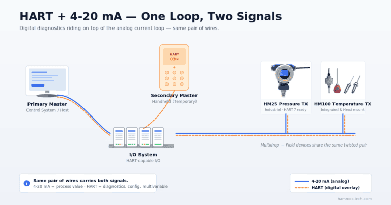
- PT (pressure transmitter): a circle with PT, providing continuous 4–20 mA, HART, or Profibus output. PT lives in PIC (pressure indicating controller) loops where the PV is modulated continuously.
- PS (pressure switch): a circle with PS plus modifier (PSH, PSL, PSHH, PSLL, PDS). PS lives in alarm and shutdown chains where the action is binary.
The same pipe header often carries both. PT-101 feeds the PIC-101 control loop, and PSHH-101 sits independently on the same line to arm the safety shutdown. Two symbols, two purposes, one process tap manifold. The device-level differences are covered in our companion article on pressure sensor versus transducer versus transmitter.
Common Drafting Mistakes & How to Avoid Them
Five errors account for most questions on shared drawings:
- Missing modifier letter. Drawing a bare PI when the device is actually a switch. The reader assumes “indicator” (operator-visible only) and forgets the device drives a shutdown. The valid switch tag is PSH or PSL, not bare PS in safety contexts.
- Reversed actuator arrow. An arrow pointing away from the contact means it trips on falling pressure. Drafters habitually draw it toward the contact for everything, and downstream that turns a low-pressure cutout into a phantom high alarm.
- PDS missing the second process connection. A differential symbol with only one tap is a regular PS with a typo. Often not caught until commissioning.
- Wrong mounting line. A field switch drawn with a solid line through the bubble tells operations the device is in the control room. Field rounds then skip it.
- NEMA glyph on an IEC-spec project. Drawings pass internal review, but the third-party inspector flags symbols on the construction set. We have walked one customer through redrawing more than sixty pressure-switch contacts on a single SEA petrochemical package because the standard was never agreed at kickoff. Decide it on day one.
The fix for all five errors is the same loop: enforce one symbol standard project-wide, and verify each setpoint against the device’s calibrated repeatability. JJG 875-2005 sets the calibration baseline for digital pressure gauges in China, and our DP transmitter calibration walk-through covers the same logic for differential setpoints, where these symbol-versus-setpoint mismatches do the most damage.
From Symbol to Real Device — Selection Notes
Reading the symbol is half the job. Choosing the physical switch is the other half. Two families dominate:
- Mechanical: spring-loaded diaphragm or piston driving a snap microswitch. Repeatability ±2 to 3 % F.S., contact rating up to 30 V DC / 1 A. Good for non-critical alarm duty.
- Electronic: semiconductor sensing element (piezoresistive or capacitive) plus PNP/NPN solid-state output. Repeatability ±0.5 % F.S. or better, programmable setpoint and hysteresis, IO-Link variants, IP65 to IP67. Required for SIL-rated loops and modern interlocks.
For new installations we deliver an electronic switch because the programmable setpoint eliminates the top drafting error above. You set the trip from the keypad, and the as-built drawing matches the device.
HMK’s HM41 compact electronic pressure switch ships with PNP/NPN outputs, IP67, and a 4-button programmable setpoint plus hysteresis. The matching HM40 electronic pressure gauge with display adds a local readout for field rounds. Both sit in the pressure switches and gauges category, the natural next stop once the symbols on your drawing make sense.
Related reading: How to Read a Pressure Gauge Correctly Every Time — analog dial basics, dual-scale traps, tell-tale needles, and 5-step calibration check from the field.
Frequently Asked Questions
What does a pressure switch symbol look like in electrical schematics?
A contact pair (NO or NC) connected to an actuator hint, typically a half-circle or bellows with an arrow showing whether rising or falling pressure trips it. The contact is drawn in its unpressurized, de-energized state.
What’s the difference between PSH and PSHH on a P&ID?
PSH is the first-tier alarm. It warns the operator when pressure crosses the high setpoint. PSHH is the independent safety-trip layer. It closes a shutdown valve or trips a motor when pressure continues rising past the alarm.
Are pressure switch symbols different in NEMA vs IEC standards?
Yes. NEMA, IEC 60617, and JIC NFPA T3.7.1 each draw the contact and actuator slightly differently. Function is identical, line work is not. For export-grade projects, IEC 60617 is the common default and is supported natively by EPLAN and the major ECAD tools.
What’s the symbol for a high pressure switch?
On a P&ID, PSH sits inside an instrument bubble. On an electrical schematic, the actuator arrow points toward the contact (closes on rising pressure). On an ISO 1219 hydraulic drawing, the rectangle’s spring arrow indicates rising-pressure actuation.
How do I read a pressure switch on an HVAC wiring diagram?
HVAC drawings use the IEC or NEMA electrical schematic family. Find the contact pair, identify NO or NC, and read the device tag. Common HVAC labels include air pressure switch, fan proving switch, and low-charge switch on refrigeration circuits.
Where can I find pressure switch symbols for CAD or EPLAN?
The Siemens Capital X panel-designer library, EPLAN’s built-in palette under ‘pressure operated’, and ANSI/ISA-5.1 cheat sheets cover the common cases. For project-specific glyphs, request the legend page from the lead drafter. Most consultants have a house style sheet that overrides public libraries.
HMK builds industrial pressure transmitters, switches, and gauges for process plants and OEM machine builders worldwide. If you’ve decoded a symbol and need the matching physical device, browse the pressure switches and gauges catalog or contact us with your project specification.
Related reading: For the gauge that pairs with the switch on lube-oil headers and pumps, see our electric oil pressure gauge guide.