DP Transmitter Calibration: 5-Point Procedure & Field Traps
Most DP transmitter calibration calls turn into a two-hour bench session because someone skipped the 5-point Up & Down loop. The mA reading looks fine at zero and full scale, but the hysteresis between rising and falling pressures is hiding a 0.05% FS lie that shows up as drift two months later in service.
The same five-point method, the milliamp math, and the re-range-versus-trim distinction apply to any loop — see our full guide to pressure transmitter calibration.
This guide walks the full procedure — equipment, the 5-point Up & Down loop, where HART changes things, the five field traps that ruin a “perfect” calibration, and the JJG 882-2019 interval rule that decides when you do this again. If you haven’t picked the transducer yet, see the low pressure transducer selection guide first. (the same code that requires a 4:1 TUR for any precision pressure sensor at 0.1 % FS)
Before you calibrate, check the turndown ratio at your chosen range, because it sets the accuracy you can actually verify. The figure you can verify is the reference term; for the full installed accuracy that also adds temperature and static-pressure effects, use our transmitter total error calculator.
What Calibration Actually Is (vs Configuration vs Trim)
Three terms get used interchangeably on shop floors. They are not the same:
| Term | What it does | When to do it |
|---|---|---|
| Calibration | Compare the transmitter’s output against a traceable standard, document the deviation | At commissioning, then per JJG 882-2019 interval; after suspected damage |
| Configuration | Set Lower Range Value (LRV) and Upper Range Value (URV) to match the application range | At commissioning; whenever the process spec changes |
| Trim | On smart (HART) transmitters, internally adjust the sensor reading or the D/A output to match a known input | Only as part of a calibration that found a deviation |
Calibration is the assessment; configuration is the range scaling; trim is the actual correction inside a HART device. A common mistake: an instrument tech “calibrates” a transmitter by changing LRV/URV when the field reading drifts. That is a configuration change masking a real deviation, and it falsifies the calibration record. If you need a refresher on what the diaphragm and capacitive cell are actually doing, the DP transmitter working principle explainer covers the mechanics that calibration is meant to verify.
For analog (non-HART) transmitters, trim happens via mechanical zero & span potentiometers. For HART transmitters, trim is a digital command sequence — Sensor Trim corrects the transducer reading, D/A Trim corrects the loop output. Both are needed for a full calibration, and the order matters (sensor first, then output).
The rest of this guide is about calibration proper — measurement and adjustment against traceable references — not range reconfiguration.
Equipment and Pre-Calibration Checks
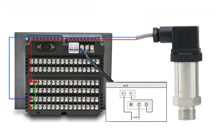
A field calibration kit needs at minimum: a pressure calibrator with accuracy class at least 3× tighter than the transmitter (so for a ±0.1% FS transmitter, use a ±0.033% FS or better calibrator), a HART communicator (475 / 375 / Smart Wireless variant, where applicable), a 4½-digit multimeter, a 24 VDC clean loop power supply, and a 250 Ω precision resistor (1% or better). The wiring topology is the standard 2-wire loop — see the 4-20 mA pressure transmitter wiring guide if you’re not sure where the resistor goes. Add wrenches sized for the impulse line fittings and a vent line for the high side.
The 3× rule matters at low ranges. The HMK HM30 micro DP with ±0.1% FS at 0–500 Pa demands a calibrator that holds ±0.16 Pa across that span. A generic ±0.05% FS class calibrator covers it, but only because that calibrator’s 0.05% is referenced to its OWN full scale (which usually exceeds 500 Pa by 10×). Always check the calibrator’s accuracy in the calibrated range you’ll use, not its nominal class.
Environment matters more than people think. Chinese national standard GB/T 28474.1-2012 specifies vibration class 1 (10–55 Hz, 1g, ±0.5% FS additional uncertainty). A bench near a compressor, an HVAC fan, or a forklift route blows that budget. Move to a vibration-free corner. Stabilize ambient temperature within ±2 °C and relative humidity below 75% for at least 30 minutes before starting.
The China Standardization for Process Pressure & Boiler (CCSPB) 2023 white paper on field calibration uncertainty puts typical field uncertainty at ±0.15% FS — three times worse than a calibration lab’s ±0.05% FS. Plan the budget. If your application’s allowable error is ±0.2% FS, a field-only cycle is marginal. Send the transmitter to a lab.
Before energizing: isolate the transmitter from the process, vent both sides to atmosphere, equalize through the manifold, and only then disconnect the impulse lines. Reverse order on reassembly. Skipping the equalize step blows the diaphragm.
The 5-Point Up & Down Procedure
Five rising points, then five falling points. Ten readings total. Anyone selling you a “5-point calibration” that only goes one direction missed the hysteresis check.
| Step | Pressure (% URV) | Expected output | Allowed dev (±0.1% FS class) |
|---|---|---|---|
| 1 ↑ | 0% | 4.000 mA | ±0.016 mA |
| 2 ↑ | 25% | 8.000 mA | ±0.016 mA |
| 3 ↑ | 50% | 12.000 mA | ±0.016 mA |
| 4 ↑ | 75% | 16.000 mA | ±0.016 mA |
| 5 ↑ | 100% | 20.000 mA | ±0.016 mA |
| 6 ↓ | 75% | 16.000 mA | ±0.016 mA |
| 7 ↓ | 50% | 12.000 mA | ±0.016 mA |
| 8 ↓ | 25% | 8.000 mA | ±0.016 mA |
| 9 ↓ | 0% | 4.000 mA | ±0.016 mA |
The Down direction is where the diaphragm hysteresis hides. In one Chinese instrumentation forum (gongkong) thread from 2024, a maintenance lead found that his Rosemount 3051 read 4.000 mA at zero on the way up and 4.025 mA at zero on the way down — 0.05% FS hysteresis that fell inside the spec sheet’s claimed ±0.075% FS accuracy class but was not visible on a 5-point one-way procedure. Six months later, that hysteresis had widened to 0.12% FS, breaching the class.
Procedure tip: hold each pressure point for 60 seconds before reading. Diaphragm strain takes 10–30 seconds to settle on first application; reading at 5 seconds gives a transient value that disagrees with the steady-state response. Use our 4-20 mA calculator to verify the expected mA at each setpoint.
Recording: write each reading in two columns (Up, Down) for each pressure setpoint. The hysteresis at any point is |Up - Down|. The maximum hysteresis across all five points is the number that goes on the calibration certificate, not the average. The cert label itself is PSID (differential) on these instruments — see the PSIA vs PSIG vs PSI cheat sheet for why specifying a single PSID transmitter beats two PSIG units differenced in software.
If the maximum hysteresis exceeds the transmitter’s accuracy class, the transmitter has failed. Either trim (smart units) or replace the sensor cell. Do not “average it out” with a configuration change — that hides the fault and falsifies the trail.
After Down completes, do a single 0% Up read again. That third zero is the post-cycle drift indicator. If it has shifted from your initial 0% Up by more than 0.05% FS, the sensor cell is unstable and a longer settling period is needed before the next attempt.
HART vs Analog: Where the Procedure Differs
For an analog transmitter (4-20 mA only, no HART) the procedure ends at step 9. Adjustment, if needed, is mechanical: a zero potentiometer and a span potentiometer behind the housing. Adjust zero, then adjust span, then re-run all five Up points to verify span shift didn’t shift zero (it usually does).
For a HART transmitter, the procedure has two correction stages:
Sensor Trim (Lower & Upper). Apply zero pressure, the HART communicator captures the present sensor reading and writes “this is zero.” Apply 100% URV, communicator captures and writes “this is full scale.” This corrects the transducer’s internal reading, not the mA output. The HMK HM3051 smart DP and HM31 DP both expose Sensor Trim through Bell 202 FSK at 1200/2200 Hz.
D/A Trim (4 mA & 20 mA). With the loop powered through your 250 Ω resistor and multimeter, the communicator drives the transmitter to output exactly 4 mA, you read the actual mA on the meter and tell the communicator the actual reading. Same for 20 mA. This corrects the digital-to-analog converter on the loop.
Order matters: Sensor Trim before D/A Trim, always. Reversed, the D/A Trim fights the sensor reading and you chase your tail.
A common analog vs HART confusion: HART’s digital reading and the 4-20 mA reading can disagree by up to 0.025 mA in normal service (specification, not a fault). This is the “primary variable digital” vs “primary variable analog” split. Trust the digital value during calibration; the analog is for legacy DCS only.
5 Field Traps That Ruin a Perfect Calibration
1. Wet-leg density not corrected. For DP level applications, the high side is filled with process or seal fluid. If you calibrate the transmitter at the bench with air on both sides, the field reading will be off by ρ × g × h of the wet leg. Always either calibrate in-place with the wet leg charged, OR enter the wet-leg density correction in HART and bench-calibrate dry. Pick one path; mixing them gives compounded errors. In one CIP retrofit at a Chinese dairy plant, a 0.997 kg/L water-filled leg was confused with a 1.030 kg/L cleaning-solution leg at re-calibration, producing a stable 3.3% offset that took two weeks to trace.
2. Isolation valve order. The manifold has three valves: high-side block, low-side block, and equalize. To isolate from process: open equalize, then close high-side block, then close low-side block. To restore: open low-side block first, then high-side block, then close equalize. Reversing this sequence blows the diaphragm with full static pressure differential. Tape this sequence to the manifold.
3. Temperature drift between bench and field. Bench at 25 °C, field at -10 °C: the HM31 typical temperature coefficient is ±0.02% FS/°C, so 35 °C gradient = 0.7% FS drift on top of zero error. Calibrate at the temperature the transmitter will actually see, or apply temperature compensation.
4. Mounting orientation. Sensitive low-range cells (≤500 Pa) shift zero by 3–8 Pa between vertical and horizontal mounts. Calibrate in the orientation the field installer used.
5. Power supply ripple. A bench-grade 24 VDC PSU has <10 mV ripple. A site PSU on a rack with VFD-driven motors can carry 100 mV. That ripple modulates the loop current at the line frequency. Use an isolated, regulated 24 VDC source for the calibration window, not the production loop.
How Often to Recalibrate
Three references compete here:
- ISO 17025 (general lab): typically 12 months, but specifies “based on stability and use,” meaning the asset owner decides.
- JJG 882-2019 (Chinese national metrology regulation for pressure transmitters): 6 months for ranges ≤10 kPa, 12 months for ranges >10 kPa. This is mandatory for any transmitter used on a regulated Chinese site.
- API 21.1 (custody transfer, oil & gas): every 12 months minimum, more frequent if proven unstable.
The 6-month rule for low ranges is field-measured, not paranoid. We tracked a HM3051 HART DP transmitter at a Chinese petrochemical plant in CIP/SIP service for six continuous months. The cumulative zero drift at the 6-month mark was +0.18% FS — well inside the JJG 0.3% FS allowance, but 60% of the available margin used in half the typical interval. Extending to 12 months on a low-range CIP service is statistically a coin flip.
Field indicator that you should pull a transmitter early: log the LRV reading (4.000 mA at zero process) at every shift handover. If three consecutive shifts show ±0.05 mA from the previous baseline (= ±0.3% FS), the unit is drifting and the next scheduled calibration window has already moved up by 30%.
A transmitter that has just survived a flood, a steam-out, an over-temperature alarm, or an SIS proof test is OUT of its previous calibration window regardless of date. Re-calibrate immediately. Related: if a high-pressure trip switch shares the same loop, the PSH/PSHH symbol on the P&ID tells you whether the switch goes to alarm or to SIS shutdown. For the full HMK differential pressure transmitter family — including the HM1151 capacitive 16-range option for level service — see the catalog page.
Quick-Reference Field Checklist
Before:
- Calibrator accuracy class at least 3× tighter than transmitter, in the calibrated range
- HART communicator charged + DD file for the device loaded
- Stable 24 VDC supply (<10 mV ripple) + 250 Ω precision resistor
- Vibration & temperature env within GB/T 28474.1 class 1 limits
- Manifold valve sequence taped to the unit
During:
- Equalize → close high → close low → vent both sides → disconnect
- 5 Up readings, hold each 60 s, record mA + tank pressure
- 5 Down readings, same hold time, same record format
- Compute hysteresis at each setpoint — flag any > 0.05% FS
After:
- Sensor Trim, then D/A Trim (HART only) — order non-negotiable
- Verify 0% reading post-cycle drift < 0.05% FS
- Sign certificate; record next-due date per JJG 882-2019 interval
- Restore: open low → open high → close equalize
FAQ
Calibration is a two-hour job done right and a two-week chase done wrong. Run the 5-point Up & Down, follow JJG 882-2019 intervals, and watch the five field traps. If you need a HART-trained tech on site for a specific protocol or a custom DP transmitter range, talk to an HMK pressure engineer.
Need a custom DP transmitter calibration certificate or a HART-trained field tech? Contact HMK — share your range, accuracy class, and HART/analog needs, and we’ll match a calibrator-grade unit and provide the JJG 882-2019 interval schedule for your service.
The manifold valve sequence trap above is rooted in the manifold type. For the upstream selection — 2-valve vs 3-valve vs 5-valve — see our valve manifold for DP transmitter guide with decision tree and HMK by-model picks.
Calibrating a DP transmitter for flow service follows the same five-point sequence as for level or pressure, but the four-condition sign-off (zero, span, static, temperature) under JJG 640-2016 is the regulatory layer specific to flow. Background on how DP becomes flow is in the DP flow measurement guide.
Related: Calibrating a temperature loop instead? See how to calibrate a temperature transmitter (RTD & TC) for the two-point trim and the 4:1 TUR rule.
Related tool: Sizing the range first? The turndown & accuracy calculator shows how turndown changes the installed accuracy of a DP cell.