FREE ENGINEERING TOOLS
4-20mA Signal Calculator
Calculate the mA output signal for any process value within a transmitter’s configured range, or determine the process value from a measured mA reading. Essential for commissioning and troubleshooting 4-20mA loop instruments.
4-20mA Calculation Formula
The 4-20mA current loop is the most common analog signal standard in industrial process control. The relationship between the current signal and the process variable is linear:
Checking a transmitter against its 4-20 mA points? Pair this calculator with our step-by-step pressure transmitter calibration procedure to confirm each point reads true.
The 4 mA baseline (called the “live zero”) is a key design feature: it allows the control system to distinguish between a transmitter reading zero and a broken wire (which reads 0 mA). A healthy 4-20mA loop should never read below ~3.8 mA or above ~20.5 mA during normal operation.
Some transmitters support extended ranges: NAMUR NE 43 defines 3.8-20.5 mA as the normal operating band, with values outside this range indicating fault conditions. Values below 3.6 mA indicate a downscale failure, while values above 21 mA indicate an upscale failure.
Worked Examples
Example 1: Pressure Transmitter Reading
A pressure transmitter is configured for 0-10 bar range (LRV=0, URV=10). The measured signal is 12 mA. What is the pressure?
PV = 0 + (12 – 4) / 16 × (10 – 0) = 0 + 0.5 × 10 = 5.0 bar
Example 2: Temperature Transmitter Signal
A temperature transmitter is configured for 0-200°C (LRV=0, URV=200). The process temperature is 75°C. What mA signal should it output?
mA = 4 + (75 – 0) / (200 – 0) × 16 = 4 + 0.375 × 16 = 10.0 mA
Example 3: Level Transmitter with Offset
A level transmitter measures 200-800 mmH₂O (LRV=200, URV=800). The signal reads 8 mA. What is the level?
PV = 200 + (8 – 4) / 16 × (800 – 200) = 200 + 0.25 × 600 = 350 mmH₂O
RECOMMENDED PRODUCTS
4-20mA Transmitters in Stock
These transmitters use the 4-20mA standard you just calculated. Paired here: one for pressure, one for temperature — both ship with factory calibration certificates.
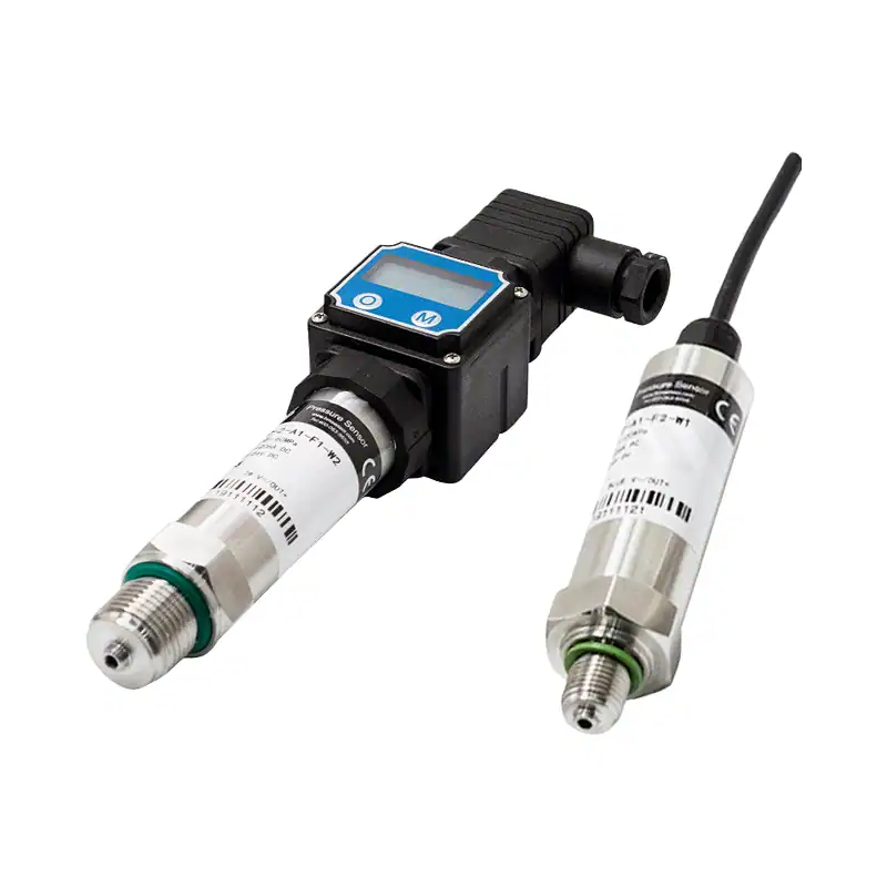
HM20 Pressure Transmitter (4-20mA)
Standard 2-wire 4-20mA pressure transmitter
- Signal: 4-20mA 2-wire, 10-36 VDC loop
- Accuracy: ±0.25% FS including linearity & hysteresis
- Ranges: Gauge, absolute, compound — 20+ options
- Process connection: G1/4, 1/2 NPT, G1/2 and more
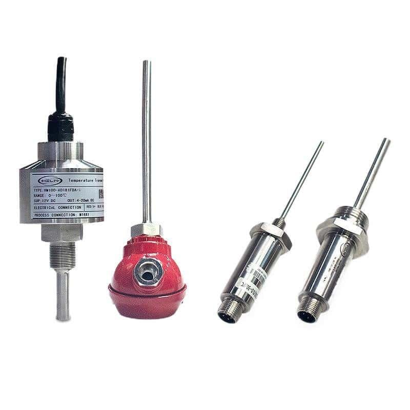
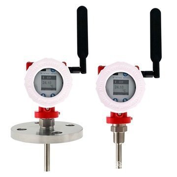
HM100 Integrated Temperature Transmitter
4-20mA temperature transmitter — universal RTD / TC input
- Signal: 4-20mA 2-wire, 10-36 VDC loop
- Accuracy: ±0.1% of span (better than 0.2% Class A)
- Input: Pt100 / Pt1000 / Cu50 / K / J / T / E / N / S / R / B
- Options: Explosion-proof Ex d IIC T6, HART
Frequently Asked Questions
Recommended Products
Professional instrumentation products that work with the calculations from this tool.
Need a 4-20mA Pressure or Temperature Transmitter?
Our transmitters output standard 4-20mA signals with configurable ranges. Available with HART, RS485, and display options. Engineers typically respond within 12 business hours.
On a 0–250 Pa transducer, 4-20 mA gives only 16 µA per Pa of resolution. The low pressure transducer selection guide explains when 0–10 V output is the better fit at low ranges.
Related tool: Working with PSI inputs but the receiving system reads bar? Use our PSI to Bar Converter for the unit step before the loop math.
Related tool: Converting a 4–20 mA signal from an orifice or venturi loop? Our DP flow calculator turns the differential pressure behind that signal into flow through the square root.
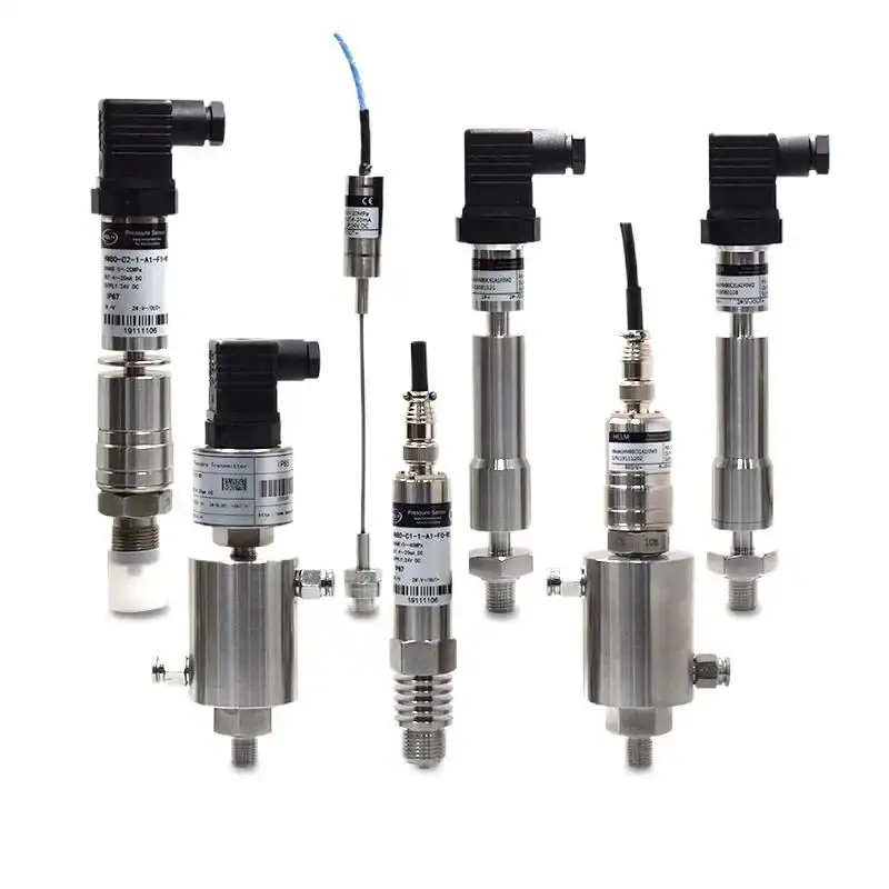
Transmitters with a 4–20 mA output

HM20 General Purpose Pressure Transmitter
Gauge or absolute ranges with ±0.25 % FS and a 4–20 mA output. The general-purpose choice for most process lines.
View details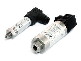
HM29 Digital Intelligent Pressure Transmitter
Digital intelligent transmitter with on-board configuration and diagnostics.
View details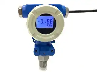
HM25 Industrial Pressure Transmitter
Industrial transmitter with HART support, built for demanding process environments.
View details