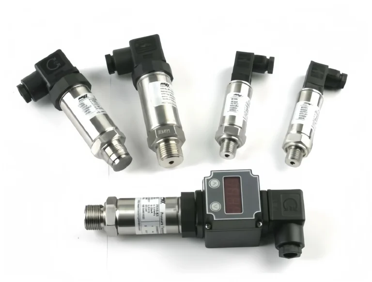
Pressure Transmitter Working Principle: 4 Types (2026)
Over fourteen years I have calibrated more than 12,000 HM-series pressure transmitters — on petrochemical skids in Gujarat, offshore platforms off Aberdeen, HVAC retrofits in Perth, and countless inland water plants here in Hangzhou. They all output the same 4-20 mA signal. Yet two years after commissioning, one transmitter still reads within ±0.05 %FS of its certificate while another has crept to ±0.5 %FS. The ten-fold gap has nothing to do with the signal. It lives in the sensing element — the diaphragm, the substrate, the electrode geometry hidden a few millimetres behind the process flange.
A pressure transmitter converts process pressure into a standardised electrical signal through three stages: a sensing element deforms under pressure, a conditioning circuit amplifies and temperature-compensates the raw millivolt output, and an output driver shapes the final 4-20 mA loop or HART telegram. Four sensing technologies dominate modern instrumentation — piezoresistive diffused silicon, ceramic capacitive, silicon-on-sapphire, and MEMS. This guide walks through all four with real drift numbers, factory QA data, and a selection framework you can use on the next RFQ.
What Is a Pressure Transmitter?
A pressure transmitter is an industrial instrument that converts process pressure — bar, psi, kPa, mmH₂O — into a standardised electrical signal a PLC, DCS, or SCADA system can read. Typical outputs are 4-20 mA (analogue current loop), HART (digital over 4-20 mA), or IO-Link / RS485 (pure digital).
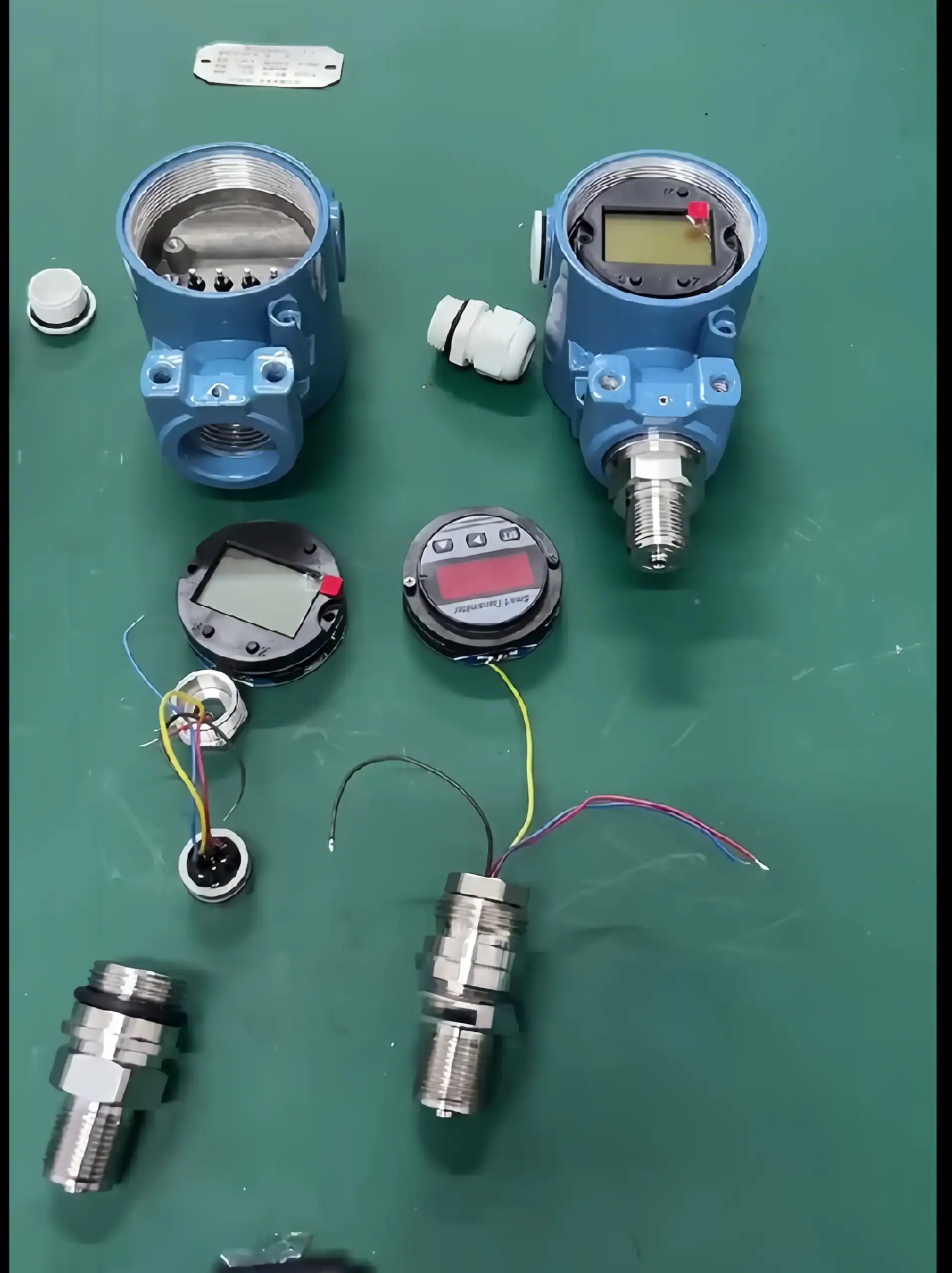
Inside every modern transmitter, three functional blocks sit in series: a sensing element (diaphragm and physical transducer that deform under pressure), a signal conditioning circuit (instrumentation amplifier, ADC, temperature compensation tables, microprocessor), and an output driver (DAC, V-to-I converter, and for HART units an FSK modem).
A pressure sensor refers to the raw transducer alone. A pressure transducer typically adds basic amplification. A transmitter packages all three blocks plus intrinsic-safety barriers. For the sensor-vs-transducer-vs-transmitter distinction, see our dedicated comparison guide.
A narrower but equally common branch point is choosing between a transmitter (continuous analog/digital signal) and a pressure switch (binary contact closure at a setpoint, with the same NPT or G/BSPP process-thread choice, drawn as a PSH/PSL bubble on the P&ID). Our pressure switch vs pressure transmitter decision guide walks through the five criteria that decide which instrument fits each loop.
The Shared Working Principle
Every pressure transmitter, regardless of sensing technology, follows the same six-step physics chain:
- Process medium pushes against an isolation diaphragm — 316L stainless for general service, Hastelloy C276 for chlorides, tantalum for very aggressive media.
- Silicone-oil fill fluid transfers pressure from the isolation diaphragm to the internal sensing diaphragm — or, in oil-less ceramic-capacitive designs, the isolation diaphragm is the sensing membrane.
- The sensing diaphragm deforms by micrometres. A typical 0–10 bar diffused-silicon diaphragm deflects roughly 5 µm at full scale.
- Deformation changes a physical property — resistance (piezoresistive, MEMS), capacitance (ceramic, silicon-on-sapphire with capacitive readout), or resonant frequency (resonant silicon).
- A Wheatstone bridge or capacitance bridge converts that change into a 0–100 mV raw signal.
- The conditioning circuit amplifies, linearises, temperature-compensates, and re-transmits as 4-20 mA or HART.
Four Sensing Technologies Compared
Of the four, the two engineers most often weigh against each other are piezoresistive and capacitive — both dominate general process pressure but behave very differently under low-pressure, high-temperature, and corrosive conditions. If that trade-off is your main decision, see our piezoresistive vs capacitive pressure sensor comparison before choosing a technology below.
Piezoresistive Diffused Silicon
Piezoresistive sensing exploits the fact that single-crystal silicon, under mechanical strain, changes electrical resistance by a factor of roughly 100× greater than a bulk metal strain gauge. During wafer fabrication, four piezoresistors are diffused into a thin silicon diaphragm and wired as a Wheatstone bridge. Two resistors sit where strain is tensile, two where it is compressive — so differential pressure produces maximum bridge output while common-mode temperature or supply variations cancel.
The silicon chip floats inside a silicone-oil filled cavity behind the isolation diaphragm. Pressure pushes the oil, the oil pushes the silicon diaphragm, and the bridge outputs around 100 mV at full scale with 10 V excitation.
Typical performance (HMK HM25 industrial, HE10 diffused-silicon):
- Accuracy: ±0.075 %FS, upgradable to ±0.05 %FS with multi-point linearisation
- Long-term stability: ±0.1 %FS per year
- Temperature drift: 0.02 %FS/°C within the compensated band
- Compensated range: −10 to +70 °C, extendable to +125 °C
- Overpressure: 3× FS without permanent shift
- Usable span: 0.4 kPa to 60 MPa
Piezoresistive is the workhorse of general industry — water, steam, compressed air, hydraulics, HVAC, and the bulk of oil-and-gas wellhead service. Weaknesses: at media temperatures above 150 °C the silicone oil expands and introduces span drift, and in wet-hydrogen service silicon is vulnerable to embrittlement.
Ceramic Capacitive
Ceramic capacitive sensors replace the silicon-plus-fill-oil sandwich with a single monolithic alumina ceramic (Al₂O₃ 96 %) diaphragm. A metallised electrode on the back face forms one plate of a parallel-plate capacitor; a second metallised electrode on a matching ceramic substrate forms the other plate. Pressure deflects the diaphragm, the inter-electrode gap shrinks, and the capacitance rises.
The geometry is tiny. Based on HMK’s own fabrication data, the baseline electrode gap is 3 µm, the circular electrode radius is 73 µm, and the zero-pressure capacitance is 50 pF. A 1 %FS pressure change at nominal range swings the capacitance by about 0.5 pF — a signal a modern capacitance-to-digital converter resolves with 24-bit headroom to spare.
Typical performance (HMK HM12, HE26):
- Accuracy: ±0.1 %FS, ±0.25 %FS for economy lines
- Long-term stability: ±0.05 %FS per year — half the drift of piezoresistive
- Temperature drift: 0.015 %FS/°C
- Compensated range: −40 to +125 °C
- Overpressure: 5× FS thanks to the stiff all-ceramic structure
- Usable span: 5 kPa to 10 MPa
A material detail that matters in high-temperature service: ceramic capacitive sensing avoids the thermal-sensitivity drift error inherent to the self-compensation circuit used in resistive sensors above 125 °C. That is why food-grade, pharmaceutical, and chlor-alkali plants migrate from diffused silicon to ceramic — long-term zero drift is the single biggest cost driver in CIP/SIP service. For hygienic flush-diaphragm builds, we normally specify the HM70 sanitary flat-membrane transmitter.
Silicon-on-Sapphire (SOS)
Silicon-on-sapphire transmitters grow a thin, epitaxial p-type silicon layer on top of a monocrystalline sapphire (Al₂O₃) substrate. The sapphire is electrically insulating, mechanically stiffer than steel, and has a thermal-expansion coefficient close enough to silicon that the stack survives thermal cycling that would crack a silicon-on-silicon chip.
The sapphire substrate anchors the silicon piezoresistor directly to a titanium or Inconel pressure membrane. There is no silicone oil. That eliminates the main high-temperature drift mechanism and pushes the usable media temperature to roughly +300 °C continuous (short-term peaks to 400 °C). For hydrogen service, sapphire also blocks the diffusion that embrittles bulk silicon.
Typical performance (HMK HM28, HE28): ±0.1 %FS accuracy, −60 to +300 °C media temperature, span 100 kPa to 250 MPa, relative cost 3–4× diffused silicon. Applications are narrow but high-value: downhole oil-and-gas logging, aerospace engine test stands, cryogenic rocket propellant lines, high-temperature steam and melt processes. When media sits above 150 °C and below 300 °C, sapphire is the default answer.
MEMS Piezoresistive
MEMS sensors use the same piezoresistive physics as industrial diffused silicon, but miniaturised. Anisotropic KOH etching on both faces of a silicon wafer carves a square membrane — typically 1.5 to 2 mm on a side, 20 to 50 µm thick — with piezoresistors ion-implanted along the edges where strain concentrates. A Pyrex glass substrate bonded underneath forms a reference vacuum cavity for absolute MEMS cells.
Because MEMS chips are fabricated at wafer scale, unit cost drops below one-tenth that of a stand-alone industrial sensor. That is why MEMS dominates automotive TPMS, white-goods appliances, medical infusion pumps and ventilators, and IoT condition-monitoring devices. Typical performance: ±0.25 %FS accuracy for consumer lines, ±0.075 %FS for metrology-grade industrial MEMS; long-term stability ±0.15 %FS per year; compensated range −40 to +85 °C; typical span 1 kPa to 10 MPa. See our OEM pressure sensor range for the MEMS-based board-level products.
MEMS is the right answer when unit economics, board footprint, and battery budget matter more than decade-long repeatability. It is not the right answer for a 20-year refinery transmitter.
Head-to-Head Comparison
The table consolidates the four technologies against the specifications that most often decide a selection review.
| Parameter | Piezoresistive | Ceramic Capacitive | Silicon-on-Sapphire | MEMS |
|---|---|---|---|---|
| Typical accuracy | ±0.075 %FS | ±0.1 %FS | ±0.1 %FS | ±0.25 %FS |
| Compensated temp | −40 to +125 °C | −40 to +125 °C | −60 to +300 °C | −40 to +85 °C |
| Overpressure limit | 3× FS | 5× FS | 3× FS | 2× FS |
| Usable span | 0.4 kPa – 60 MPa | 5 kPa – 10 MPa | 100 kPa – 250 MPa | 1 kPa – 10 MPa |
| Long-term drift / yr | ±0.1 %FS | ±0.05 %FS | ±0.1 %FS | ±0.15 %FS |
| Relative cost | 1.0× | 1.2× | 3.5× | 0.3× |
| HMK models | HM25 / HE10 | HM12 / HE26 | HM28 / HE28 | OEM |
Ceramic capacitive leads on overpressure and annual stability. Sapphire is the only option above 150 °C. Piezoresistive is the all-rounder. MEMS wins on cost and board area.
Signal Conditioning — How 4-20 mA Is Actually Generated
The sensing element only produces a few tens of millivolts. Turning that into a linear, temperature-compensated 4-20 mA loop current is the job of the conditioning chain. Most modern transmitters follow this sequence:
- Instrumentation amplifier (INA, gain 100–500) raises the bridge output to about 0–5 V.
- 24-bit Σ-Δ ADC digitises the signal at 100 Hz or faster.
- Microprocessor applies a two-dimensional calibration map — pressure vs. temperature — stored in EEPROM. Factory calibration normally sits at four temperature points (−40, 0, +25, +85 °C) and five pressure points (0, 25, 50, 75, 100 %FS). The MCU interpolates between them.
- DAC outputs the corrected value as a 0–5 V analogue signal.
- Voltage-to-current converter drives 4 mA at 0 %FS and 20 mA at 100 %FS. A 2-wire topology runs loop power and signal over the same pair; 3-wire adds a dedicated ground; 4-wire separates power and signal loops for galvanic isolation.
- HART FSK modem (optional) superimposes a 1200 / 2200 Hz digital modulation on the 4-20 mA, carrying diagnostics, range, and tag without disturbing the analogue loop.
The receiver reads the current across a 250 Ω shunt resistor, which converts 4-20 mA into 1–5 V. The live-zero offset is deliberate: 0 mA signals a broken loop, distinct from a legitimate zero-pressure reading at 4 mA. For 2- / 3- / 4-wire diagrams and polarity rules, see our 4-20 mA wiring guide and HART vs 4-20 mA comparison.
Inside the Factory: 3 Tests Every HMK Transmitter Passes
No matter how perfect the sensing element, what leaves the factory gate has to survive three independent tests. These are the tests our QC line runs on every serial number before packing:
- Sealing test. The transmitter is pressurised to 1.5× the upper range value and held for 30 minutes. Any decay faster than 0.1 %FS per minute fails the part to rework. This catches isolation-diaphragm pinholes and O-ring damage that bench calibration cannot see.
- Insulation resistance. With power disconnected, power terminals, output terminals, and housing ground are measured pairwise. Minimum pass criterion: ≥ 100 MΩ at 500 V DC for 60 s. This screens for moisture ingress, damaged potting, and frayed internal leads.
- Withstand voltage / dielectric strength. 500 V AC 50 Hz is ramped from zero to the test voltage, held for 60 s, then ramped down. Leakage current must remain ≤ 5 mA throughout. This test certifies the transmitter against inductive transients on the plant bus.
Together these three tests hold the outgoing defect rate below 0.3 %.
Choosing the Right Working Principle for Your Application
Selection comes down to four questions, asked in this order:
- Media temperature? Up to +125 °C → any of the four technologies. +125 to +300 °C → silicon-on-sapphire (HM28) or the HM26 high-temperature series. Above +300 °C → a specialty melt-pressure transmitter (HM80).
- Media chemistry? Clean water, oil, air, steam → piezoresistive (HM25, HE10). Corrosive acid/alkali, slurry, food/pharma CIP → ceramic capacitive or anti-corrosive flush-diaphragm (HM50, HM70). Hydrogen or high-radiation service → silicon-on-sapphire (HM28).
- Accuracy budget? ±0.05 to ±0.1 %FS → piezoresistive or ceramic. ±0.25 %FS → MEMS or economy-grade piezoresistive. Metrology (±0.025 %FS) → special calibration service required.
- Installation style? Direct-mount process connection → standard transmitter. Remote seal with capillary type diaphragm — for high-temp, crystallising, or distant tap points → same sensing principle, capillary-filled stem up to 10 m. Hydrostatic level — a standard gauge-pressure transmitter reads P = ρ · g · h; for closed tanks or density compensation use a differential pair. See our differential pressure transmitter working principle guide. For open-tank or wet-well duty, a submersible level transmitter is often the simpler implementation of this same hydrostatic principle.
Common selection mistakes we see: specifying piezoresistive for 180 °C steam (span drifts within a month), specifying MEMS for 20-year refinery service (drift outgrows calibration interval), specifying sapphire for room-temperature tap water (3× overspend).
Frequently Asked Questions
A pressure transmitter converts process pressure into a standardised electrical signal (4-20 mA, HART, or IO-Link) through three stages. First a sensing element — a thin diaphragm backed by a transducer — deforms under pressure. Second a signal-conditioning circuit amplifies, linearises, and temperature-compensates the raw millivolt output. Third an output driver shapes the result into the final 4-20 mA loop current or digital telegram. The four mainstream sensing principles are piezoresistive diffused silicon, ceramic capacitive (3 µm electrode gap, 50 pF baseline), silicon-on-sapphire, and MEMS. All four produce the same 4-20 mA downstream but differ by an order of magnitude in long-term drift, overpressure, and high-temperature stability.
The sensing element — a Wheatstone bridge for piezoresistive or MEMS designs, a capacitance bridge for ceramic or silicon-on-sapphire — converts diaphragm deformation into a 0–100 mV raw signal. An instrumentation amplifier, a 24-bit Σ-Δ ADC, a microprocessor applying a factory-stored temperature-compensation map, and a voltage-to-current converter then scale the signal to 4 mA at zero pressure and 20 mA at full scale. The current loop runs through the transmitter, the field cable, and a 250 Ω shunt resistor at the receiver, which reads back 1–5 V (live-zero). A reading of 0 mA therefore signals a broken loop, distinct from a legitimate zero-pressure reading. For full topology wiring, see our 4-20 mA wiring guide.
Four technologies dominate modern instrumentation. Piezoresistive diffused silicon — the general-purpose workhorse — delivers ±0.075 %FS accuracy across 0.4 kPa to 60 MPa. Ceramic capacitive uses a 3 µm electrode gap on an alumina diaphragm and earns ±0.05 %FS annual stability in corrosive or high-temperature chemical service. Silicon-on-sapphire is the only practical option above 150 °C, reaching 300 °C continuous. MEMS miniaturises piezoresistive sensing onto a 2 mm silicon die at one-tenth the cost, dominating OEM, automotive, and IoT applications. Each technology converts pressure to electricity differently, but the downstream 4-20 mA output is identical.
From 12,000-plus field calibrations, the six issues I see most often are: zero drift from diaphragm fatigue after roughly 10⁷ pressure cycles; span shift from silicone fill-oil thermal creep above +100 °C; moisture ingress through the reference vent tube on gauge-type models; overpressure damage when reciprocating-pump installations lack a pulsation dampener; loop failure from ungrounded cable shields picking up VFD harmonics; and clogged impulse lines on slurry service. The standard troubleshooting order is: verify the loop current at the transmitter, then at the receiver, then re-zero and re-span with a reference calibrator before replacing any hardware.
Not directly. A differential-pressure (DP) transmitter produces a flow reading when paired with a primary element — orifice plate, venturi, Pitot tube, or averaging flow element. Flow rate follows Q = K × √ΔP, so the DP transmitter’s output must be square-root-extracted either in the transmitter firmware or in the DCS. The same DP sensing principle also measures liquid level, density, and interface — see our DP transmitter working principle guide for the physics and installation tips.
Related reading: How to Read a Pressure Gauge Correctly Every Time — analog dial basics, dual-scale traps, tell-tale needles, and 5-step calibration check from the field.
Conclusion
Four sensing technologies, one 4-20 mA output, ten-fold differences in long-term drift. Pick by media temperature first, chemistry second, accuracy third, installation style last. HMK covers all four technologies across the HM and HE series — HM25 / HE10 diffused silicon, HM12 / HE26 ceramic capacitive, HM28 / HE28 sapphire, and OEM MEMS on request. If you’d like help specifying for a specific application, our engineering team is one email away — send us your application brief.
For hazardous-area variants of this principle, see the Ex i intrinsic safety guide.
For pressures below one atmosphere, see the vacuum gauge guide — it covers the five sensor technologies (capacitance, Pirani, thermocouple, Bourdon, cold cathode) that take over where standard pressure transmitters lose accuracy.