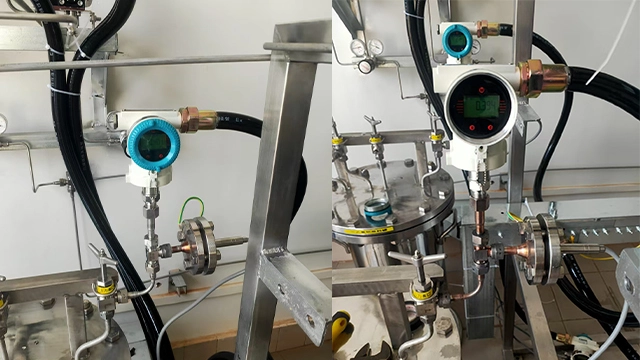
4-20mA Pressure Transmitter Wiring: 2-Wire, 3-Wire & 4-Wire Guide
You’ve got a new 4-20mA pressure transmitter in hand and you need to wire it correctly the first time — without frying the board, starving the loop of voltage, or spending three hours debugging why the PLC reads zero.
Once the loop is wired, the next step is confirming it reads true — see the step-by-step pressure transmitter calibration procedure.
Related: Beyond the wiring, the output type itself is a choice – 4-20 mA versus 0-10 V, 1-5 V, and RS485 are compared in pressure transmitter output signals.
Here’s the short version before we get into the diagrams: in about 90% of industrial pressure-transmitter installations, 2-wire loop-powered wiring is the right choice. Not because it’s the cheapest — because the other configurations only earn their place when one of three specific conditions is met. This guide walks you through the three wiring diagrams, the voltage and load-resistance math you actually need, and the five mistakes we see most often when customers send units back for “not working” — when the unit is fine.
1. The Quick Decision Framework
Before you look at a single diagram, answer these three questions. The first “yes” tells you which wiring type you need:
- Does your transmitter draw more than ~40 mA, or does it contain a powered display, relay outputs, or onboard data logger? → 4-wire.
- Do you need full galvanic isolation between power and signal — because the loop crosses between grounded systems, or code requires it? → 4-wire.
- Does the transmitter need independent power because it has a local display or alarm relay, but the signal can still share a common with power return? → 3-wire.
- None of the above? → 2-wire loop-powered. This covers most pressure, level, and temperature transmitters in normal process service.
That’s it. The rest of this guide is about wiring each option correctly — and not making the five mistakes at the end. If you’re not sure whether you need absolute or gauge pressure reference for your loop, sort that out first — the wiring is the same either way, but the wrong reference type will give you wrong readings no matter how clean your loop is.
One more upstream check before picking a wiring topology: make sure a transmitter is what this loop actually needs. If the PLC only cares about a single trip point, a switch is two wires to a DI card and the job is done. See our pressure switch vs transmitter wiring comparison for the side-by-side on conductor count, fail-safe behaviour, and when one beats the other on a retrofit.
2. 2-Wire (Loop-Powered) 4-20mA Pressure Transmitter Wiring
A 2-wire transmitter uses the same two conductors for both its DC supply and its current signal. The transmitter acts as a variable current sink, modulating the loop current between 4 mA (zero of range) and 20 mA (full scale). Power and signal share the same wires — that’s why this configuration is also called loop-powered.
Wiring diagram (2-wire)
  24 VDC (+) ──────── Transmitter (+)
                       Transmitter (−) ──────── PLC AI (+)
                                                 │
                                              [ 250 Ω ]   ← load resistor
                                                 │         (often inside the PLC card)
  24 VDC (−) ──────────────────────── PLC AI (−) ┘
Voltage budget math
This is where most 2-wire loops fail. The formula is straightforward:
Vsupply ≥ Vtransmitter,min + (0.020 A × Rtotal)
For an HMK HM20 with Vmin = 12 V and a 250 Ω load: V_supply ≥ 12 + (0.020 × 250) = 17 V.
A standard 24 VDC supply gives you 7 V of headroom — enough for cable resistance and a HART barrier in series. At 24 V the maximum allowable loop resistance is (24 − 12) / 0.020 = 600 Ω, which is plenty for most runs. If you’re running 500+ meters of thin cable, add the round-trip cable resistance to Rtotal and recheck. Our 4-20mA loop calculator does this math for you — plug in supply voltage, load resistance and cable length.
Use 2-wire for: gauge, absolute and differential pressure transmitters in normal process service. The HMK HM20, HM22, HM25, HM27 and HM70 are all 2-wire loop-powered. It’s also the only configuration compatible with standard intrinsic-safety barriers.
3. 3-Wire 4-20mA Pressure Transmitter Wiring
A 3-wire transmitter splits power and signal: two wires bring in DC power, and a third wire carries the current signal back to the PLC. Signal and power return share a common ground — that’s the key difference versus 4-wire.
Wiring diagram (3-wire)
  24 VDC (+) ──────── Transmitter V+
  24 VDC (−) ──┬───── Transmitter COM
               │
               │      Transmitter SIG ──────── PLC AI (+)
               │
               └──────────────────────────────── PLC AI (−)
You’ll see 3-wire on pressure transmitters that carry a local display, HMI pushbuttons, or high/low alarm relays — anything that needs more power than a 2-wire loop can source. Because the transmitter no longer has to “steal” power from the loop, it can run a fuller feature set.
4. 4-Wire (Self-Powered) 4-20mA Pressure Transmitter Wiring
A 4-wire transmitter has fully isolated power and signal pairs. Two wires for power (often 110/220 VAC, sometimes 24 VDC), two wires for the 4-20 mA signal going to the PLC. There is no shared ground between the two pairs.
Wiring diagram (4-wire)
  Line (L) ──────── Transmitter L
  Neutral (N) ───── Transmitter N          ← power pair (isolated)

  Transmitter SIG (+) ──── PLC AI (+)
  Transmitter SIG (−) ──── PLC AI (−)      ← signal pair (isolated)
Use 4-wire when:
- the transmitter is AC-powered (line-powered analyzers, many sanitary flow meters)
- you need full galvanic isolation — for example, a loop crossing between separately earthed systems, or a safety-critical measurement where a power-side fault must not propagate to the control system
- the device consumes significantly more than 40 mA and cannot be loop-powered
4-wire is overkill for most pressure applications, and the extra cabling costs are real when you’re running hundreds of meters. Reserve it for the cases above. If you’re dealing with high-temperature environments, choosing the right sensor matters more than the wiring type — the loop configuration is usually 2-wire regardless.
5. 2-Wire vs 3-Wire vs 4-Wire: Comparison Table
| Criterion | 2-Wire (Loop-Powered) | 3-Wire | 4-Wire |
|---|---|---|---|
| Power source | From 4-20 mA loop itself | External DC, shared ground | Fully isolated power pair |
| Signal isolation | None | Partial | Full galvanic |
| Power budget | ≤ ~40 mA | Moderate | Unlimited (AC or DC) |
| Cable cost | Lowest ✓ | Medium | Highest |
| HART support | Yes (standard) ✓ | Device-dependent | Device-dependent |
| IS barrier compatible | Yes ✓ | Rarely | Rarely |
| Typical use | Pressure, level, simple temp | Transmitters with display/relays | AC-powered analyzers, high-power devices |
6. Does Your PLC Card Power the Loop? Check Before You Wire
This is the single most common mix-up we see on customer returns — and none of the top-ranking guides explain it clearly.
Some analog input cards have built-in loop excitation: they supply 24 V to the transmitter internally, so you wire the 2-wire transmitter straight into the card terminals and you’re done. Most cards, though, do not supply loop power — you need a separate 24 VDC supply in series with the transmitter and card. Wire a 2-wire transmitter into one of these cards without external power and you’ll read a flat 0 mA no matter what pressure the process is at.
Here’s how the three most common PLC platforms handle it:
- Allen-Bradley 1769-IF4 / 1756-IF8: no internal loop excitation. You must wire an external 24 VDC supply in series. The module accepts the 4-20 mA signal passively.
- Siemens SM 1231 AI (S7-1200): no internal loop excitation either. You can switch each channel between voltage and current mode in TIA Portal, but the card itself does not power the transmitter — external 24 V required.
- Mitsubishi Q64AD / FX5-4AD: same story — no internal excitation. External 24 VDC supply in the loop.
HART note: if you plan to use HART communication on the same 4-20 mA loop, you need a total loop resistance between 230 Ω and 600 Ω, and a supply voltage of at least 17 V after all voltage drops. Most 24 V systems handle this fine; 12 V systems will not.
7. The 5 Wiring Mistakes That Kill Most 4-20mA Loops
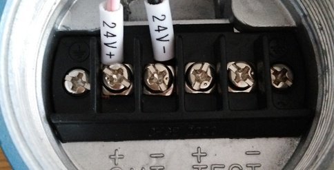
- Reversed polarity on a 2-wire transmitter. Modern units have reverse-polarity protection that prevents damage, but the loop will still read 0 mA. If the reading is stuck at zero, swap the leads before you assume the unit is dead.
- Shield grounded at both ends. This creates a ground loop and injects hum into the signal — sometimes enough to swing the reading by 0.2 mA. Rule: bond the shield at the control-panel end only.
- Total loop resistance too high for the supply. Long cable runs, extra isolators, or a HART barrier in series can push Rtotal past what your 24 V supply can drive. Recompute the voltage budget from Section 2 with every series device added.
- Wiring a 2-wire transmitter as if it were 3-wire. The loop stays open and the PLC reads 0 mA. The transmitter terminal labeled “SIG” on a 3-wire device doesn’t exist on a 2-wire device — don’t invent one.
- No breakout point for a HART communicator. If you’ll ever configure, trim or diagnose the device with a 475 or a mobile HART modem, leave a disconnect terminal or test jack in the loop. Cutting a wire in the field to clamp on a 250 Ω resistor is not a service method.
8. Pick the Right HMK Pressure Transmitter for Your Wiring
Every HMK pressure transmitter supports standard 2-wire 4-20 mA output, so any of these drops straight into a loop-powered installation:
The default workhorse. 2-wire, HART-ready on request. Covers vacuum to 100 MPa.
View HM20 specs →Same platform as HM20 with tighter accuracy. For custody transfer and lab-grade work.
View HM22 specs →2-wire with HART standard. Field-mount housing built for DCS integration.
View HM25 specs →2-wire, IS-certified versions available. Built for vacuum and absolute measurements.
View HM27 specs →2-wire with HART. Tri-clamp mounting for food, dairy, and pharma lines.
View HM70 specs →Need help sizing your loop?
Send us your PLC model and cable run length — we’ll verify the voltage budget before you buy.
Request a Quote →Before that 4-20 mA signal ever reaches your PLC, it starts at the sensing element — and the two dominant technologies (piezoresistive silicon and capacitive ceramic) behave very differently under pressure, temperature, and vibration. For a closer look at the sensing element behind the 4-20 mA signal, read our comparison before specifying your next transmitter.
Frequently Asked Questions
For wiring 4-20 mA loops in classified areas, see the Ex i barrier placement and entity-parameter rules.
On 0–250 Pa transducers, 4-20 mA resolution becomes a constraint of its own (16 µA per Pa). The low pressure transducer selection guide covers when 0–10 V output is the better fit.
Once the 4-20 mA loop is wired and powered, the next step is calibration. See our DP transmitter calibration guide for the 5-point procedure, the 250 Ω resistor placement during calibration, and 5 field traps that ruin a “perfect” calibration.
After the 4-20 mA loop is wired, the impulse-line side ends at the manifold. See our valve manifold for DP transmitter guide — when to spec 3-valve vs 5-valve and the operational sequences for each.
If your 4-20 mA loop measures sub-atmospheric pressure, read the vacuum gauge guide first — sealed-gauge transmitters show negative numbers in vacuum service, but those numbers are not actual vacuum.
If your 4-20 mA loop reads a DP transmitter wired to an orifice or V-cone, the DP flow measurement guide covers the upstream physics, primary-element selection, and the square-root extraction problem that defines DP loop turn-down.
If your 4-20 mA loop reads a fluctuating oil pressure gauge on a hydraulic press, lube circuit, or generator, work the five-cause field troubleshooting tree first — wiring or transmitter drift is one bucket, but the loop check rules out three of the five causes in the first ten minutes.
If the wiring checks out and the loop still reads wrong, our pressure transducer troubleshooting guide takes it from the symptom you see.