Oil Pressure Gauge Fluctuating: 5 Causes and Field Fixes
The oil pressure gauge on a hydraulic press, a standby generator, or a lube circuit started fluctuating, and the maintenance crew needs to know fast whether the system is failing or the gauge is just lying. We will run a five-minute decision tree, walk through the five causes that account for nearly every fluctuating reading, list the maintenance-kit tools that solve them, and finish with a red / yellow / green operations-safety table.
5-Minute Decision Tree: Where Is the Fault?
Before pulling pumps or filing a CMMS work order, work through this triage. Almost every fluctuating-gauge fault traces to one of three buckets: the gauge or transmitter itself, the wiring loop or sender, or the oil system upstream. The three quick checks below isolate which one in under five minutes; we recommend running them in order.
- Step 1, level check. On industrial reservoirs, look at the sight glass or low-level switch. On engines, pull the dipstick. If level is below the minimum mark, you are looking at Cause 1; top up and observe the gauge for three minutes.
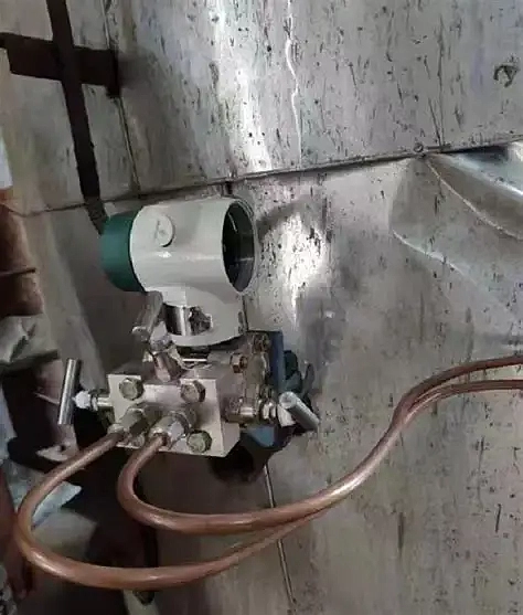
- Step 2, signal-loop check. For a 4-20 mA pressure transmitter, clamp on a loop calibrator and read mA at the source; out-of-range or noisy mA points to Cause 5. For a resistive sender driving a dashboard or panel gauge, ohm out the sender end-to-end. Most automotive oil-pressure senders sit between 10 Ω at zero pressure and 180 Ω at full scale. Industrial systems generally use 4-20 mA transmitters and skip resistive senders entirely, so on a plant loop the mA check above replaces the resistance test.
- Step 3, mechanical cross-check. If steps 1 and 2 are clean, install a master gauge in a spare port on the same line. A steady master-gauge reading with a fluctuating control-room display means the fault is on the transmitter or sender side; a fluctuating master gauge means the oil system itself is the culprit (Causes 2 through 4).
In practice, the level check resolves the majority of these calls before any tools come out; the loop check picks up most of the rest, and the mechanical cross-check is the safety net for the few that fall through. The decision tree saves you from pulling a pump on what turns out to be a corroded ground lug.
Cause 1: Low Oil Level (Most Common)
Symptom: pressure jumps the most at low flow, at the bottom of a hydraulic cycle, right after a press tonnage drop, or at engine idle. Steadies out at higher pump speed because flow refills faster than the leak rate.
Why it happens: oil level below the reservoir alarm setpoint or the sump MIN line lets the pump intake uncover during transient flow demands or vibration. On an industrial hydraulic reservoir, the risk peaks when a large cylinder extends rapidly under high flow demand, pulling reservoir level momentarily lower; the strainer can suck air across each cycle if the level was already marginal. Typical reference pressures: industrial lube headers run 30 to 60 psi; hydraulic working circuits run 100 to 250 bar; engine oil at idle is 10 to 25 psi gasoline and 30 to 40 psi diesel.
Field fix: top off to the upper sight-glass mark or dipstick MAX with the manufacturer-specified grade, run the pump for three minutes, and watch the gauge. If oil consumption explains the loss, the next conversation is about a leak; log it before walking away.
Cause 2: Wrong or Degraded Oil Viscosity
Symptom: pressure reads correctly cold then drops or fluctuates as the system reaches operating temperature, or the reverse on a cold-soaked startup.
Why it happens: viscosity that is too low at operating temperature lets bearing or clearance-flow paths bleed off the pressure the pump is trying to maintain. Common industrial causes include using ISO VG 32 in a system spec’d for VG 46, water ingress from a leaking heat-exchanger turning the oil into an emulsion, or process leakage diluting hydraulic fluid. The engine equivalents are using 5W-20 in a 5W-30 application or fuel dilution from short-trip operation.
Field fix: pull a sample into a clean bottle and inspect it. Chocolate-milk color means water in the oil and points at a heat-exchanger leak (industrial) or a head gasket (engine). If the sample is clear but smells of process or fuel, change to spec viscosity and recheck. The OEM datasheet is the authoritative reference for grade selection; vendor recommendations sometimes prioritize cost over bearing life.
Cause 3: Failing Oil Pump
Symptom: oil level and viscosity confirmed good, the gauge still fluctuates, pressure recovery is slow at startup.
Why it happens: gear or vane wear opens internal pump clearances, the suction strainer is partially blocked, or a suction-line crack draws air. On an industrial lube circuit, look at gear pumps that have run thousands of hours with degraded oil; on engines, the same wear pattern shows up after 200,000+ km.
Field fix: confirm with the mechanical cross-check from the section below. If the master gauge mirrors the fluctuation, the oil system has a real problem and the pump is the leading suspect. Pump replacement is shop work, not field repair. Until the pump can be pulled, run the system at reduced load, isolate the line if the design allows, and schedule the swap during the next planned outage. The vehicle equivalent is driving at low RPM to the nearest competent shop. Do not load the system.
Cause 4: Clogged Oil Filter or Strainer
Symptom: similar to a failing pump, often paired with a filter-bypass differential indicator showing high or in alarm.
Why it happens: skipped service intervals load the filter media. The bypass valve opens at a typical 8 to 25 psi differential, dumping unfiltered oil downstream and giving you erratic pressure as the bypass cycles open and closed under load.
Field fix: change the filter element together with the oil charge; never just swap the filter on used oil. After replacement, shorten the next change interval by 25% until you understand why the filter loaded early. If the system has a differential-pressure indicator on the filter housing, log its reading on the next pump cycle as a trend datum.
Cause 5: Sender, Wiring, Transmitter, or Gauge Itself
Symptom: master gauge reads rock-steady, but the dashboard or DCS display dances. The fault is electrical, not hydraulic.
Four sub-causes, in order of frequency on industrial systems:
- Pressure transmitter zero or span drift: most common after several years of service. The 4-20 mA loop reads out of calibration band; a loop calibrator confirms by injecting known mA at the transmitter terminals.
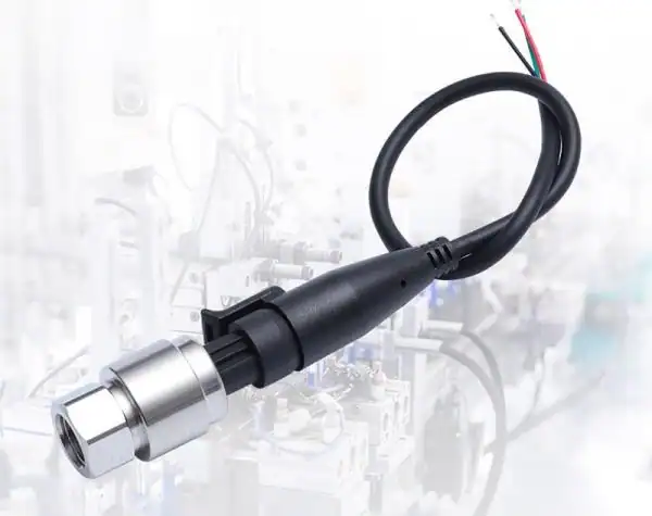
- Sender unit on resistive systems: the diaphragm cracks or the wiper contact corrodes. Test with a multimeter against the OEM resistance curve; replace if out of spec.
- Wiring or connector: a loose ground lug or oxidized terminal on the loop causes the classic high-frequency flutter that looks scary but reads correctly on a master gauge.
- Gauge itself: rare. Stuck or worn dashboard movements on older vehicles, or a digital LCD with corrupted scaling, both fall here.
Automotive note: the same five sub-causes apply on engines and small generators. Resistive senders fail more often than 4-20 mA transmitters, and a corroded ground at the engine block is the single most common dancing-needle cause on older vehicles.
Field fix: clean the loop terminals and ground first; that step alone resolves a meaningful share of these calls without parts. If the loop is clean, swap in a known-good transmitter or sender. Wiring rework and gauge replacement are last-resort steps because they usually require panel removal. If the sender keeps failing every few years, consider migrating to a 4-20 mA transmitter; see Electric Oil Pressure Gauge: Mechanical vs Sender vs Digital for the selection framework.
Mechanical Cross-Check: Confirm Real Pressure in 4 Steps
This is the highest-confidence diagnostic in our framework. A master mechanical gauge installed in a port on the same line reports actual oil pressure with no electronics in the loop, so it splits the transmitter side from the oil-system side cleanly.
- Step 1: Isolate or shut down the system, locate a spare port on the same line as the suspect gauge (typical industrial choices: a tapped tee, a bleed valve, the impulse line of a transmitter manifold).
- Step 2: Install the master gauge with a matching adapter. Industrial fittings vary: 1/4 NPT, 1/2 NPT, G1/4 BSP, and M20×1.5 are the most common. Automotive senders use 1/8-27 NPT or M14×1.5.
- Step 3: Restart the system, run at the load condition where the fluctuation appears, and read the master gauge.
- Step 4: Compare to the loop spec. If the master is steady inside spec, the dashboard or transmitter is the fault. If the master also fluctuates, the oil system has a real problem.
A master gauge with a basic adapter set is worth more diagnostic information than an hour of forum reading.
Tools You Will Need in the Maintenance Kit
Five causes, five tools — our recommended kit list. Keep these on hand and most fluctuating-gauge calls become 15-minute jobs.
| Cause | Tool | Notes |
|---|---|---|
| Cause 1, low level | Sight-glass cleaner, dipstick rag, spare oil to spec | Already in the maintenance closet |
| Cause 2, viscosity | Sample bottle, lab service or hand-held viscometer | Service charge only |
| Cause 3, pump | Master mechanical gauge with adapter set | The single most useful tool on this list |
| Cause 4, filter | Differential-pressure gauge, replacement filter element | Standard service item |
| Cause 5, transmitter / sender | Multimeter, 4-20 mA loop calibrator (e.g., Fluke 754) | Already in any instrumentation kit |
A single master gauge with an adapter kit covers Step 3 of the decision tree and the cross-check below; everything else is already at hand for routine service.
Is It Safe to Keep Running? Red / Yellow / Green Operations Table
When the gauge starts dancing during a production shift, the operator has to decide in seconds whether to stop the line. Use this table.
| Color | What you see | Action |
|---|---|---|
| RED | Pressure drops to zero, OR low-pressure trip alarm latched, OR fluctuation paired with abnormal pump or bearing noise | Trip the line. Stop the press, shut down the generator, isolate the gearbox. Continued operation will scrap the pump or bearings. |
| YELLOW | Pressure dances but never hits zero or trip-band, alarm not latched, no abnormal noise | Run at reduced load. Log the event for trending in your SCADA or data historian, schedule the cross-check inside the shift, fix the same day. |
| GREEN | Master-gauge cross-check confirms steady real pressure; only the control-room display dances | Continue normal operation. Replace the transmitter or fix wiring at the next planned outage. The system is fine. |
Automotive equivalent: RED is “stop now, call a tow”; YELLOW is “drive at low RPM to the nearest shop”; GREEN is “keep driving, fix the sender at the next service stop.”
Plant Case: 1,000-Ton Hydraulic Press
A representative case from a Tier-1 automotive supplier illustrates the full framework. The press operator reported the 0–25 MPa hydraulic-circuit gauge bouncing through ±15% during the down-stroke. Production was on time, but the operator flagged a maintenance request inside the shift.
The maintenance team walked the decision tree. Step 1 (level check): sight glass full, no level alarm. Step 2 (transmitter loop check): the 4-20 mA loop read clean from transmitter to PLC, ruling out a transmitter or wiring fault. Step 3 (master-gauge cross-check): a master gauge installed on the manifold isolation port showed the same fluctuation pattern under press load. The fault was hydraulic, not electrical.
Root cause turned out to be a partially seized pressure-relief valve oscillating around its set point, dumping flow under the down-stroke peak and starving the gauge tap. A relief-valve overhaul cleared the symptom; the transmitter was healthy.
The lesson generalizes: do not condemn the gauge or the transmitter until the master-gauge cross-check confirms the oil system. Many crews replace healthy transmitters before learning to cross-check first; building the cross-check into the second step of every fluctuating-gauge work order avoids that waste. For long-term monitoring on systems like this, see Pressure Transmitter Types and 4-20 mA Pressure Transmitter Wiring.
Frequently Asked Questions
Should oil pressure fluctuate during normal operation?
Slight movement is normal. Pressure typically drops a few psi during transient flow demand and rises with pump speed or load. What is not normal is the needle bouncing through more than 25% of full scale, or pressure dropping to zero at any point.
Can I keep running the press with a fluctuating oil pressure reading?
Refer to the red / yellow / green table above. Pressure to zero or alarm latched means trip the line; dancing-but-not-zero means reduced-load operation while you cross-check; master-confirmed-steady means it is the transmitter or display and the press can run normally.
How do I know if it is the gauge or the system itself?
Run the mechanical cross-check above. The master gauge bypasses the electronics and reads actual oil pressure. Steady master with a fluctuating display means transmitter or sender. Fluctuating master means the oil system has a real problem.
What is the normal oil pressure range?
Industrial lube circuits typically run 30 to 60 psi at the header; hydraulic working circuits run 100 to 250 bar at full pressure; engine oil at idle is 10 to 25 psi gasoline or 30 to 40 psi diesel. Always read the OEM spec for the loop you are working on.
Can a clogged oil filter cause fluctuating gauge readings?
Yes. The filter bypass valve opens at a typical 8 to 25 psi differential and cycles open and closed under load, which shows up as erratic pressure. Change the filter element together with the oil charge; never just swap the filter on used oil.
If your reading drops below zero (intake vacuum side of the gauge), the trouble-shooting tree is different. See Negative Pressure Gauge Applications for normal intake-manifold vacuum ranges and when a true negative reading indicates a system issue versus normal operation.
Industrial lubrication system? If a fluctuating dial gauge on a press, generator, or gearbox is costing you uptime, send your spec sheet for a 4-20 mA transmitter recommendation in 24 h. Get in touch →
For the same fluctuating problem on a 4-20 mA transducer rather than a mechanical gauge, see our pressure transducer troubleshooting guide.