Pressure Transducer Troubleshooting: A Symptom-First Field Guide
When a pressure transducer reads wrong on shift, you do not have time to read a parts catalog. You have a loop that is misbehaving, a multimeter in your hand, and a decision to make: re-zero it, rewire it, or pull it and raise a replacement. Most field guides sort their advice by cause, which is fine if you already know the cause. You usually do not. So this guide follows the way you actually search: by the symptom in front of you. Match what you see, work the short diagnostic sequence, and you will land on a fix or a clear call to replace.
A word before you open the housing: the transducer itself is the least likely culprit. In our field work the wiring, the power, and the impulse line cause most of the “bad transducer” calls we get. Start there.
Start Here: Match Your Symptom
Use this map to jump straight to your section. Read the first check first, then go to your symptom. Across the loops we commissioned over the years, this order finds the fault faster than working through a cause list.
| What you see on the loop or display | Go to |
|---|---|
| Loop reads 0 mA, nothing at all | No Output |
| Output stuck near 4 mA, will not rise with pressure | Stuck at 4 mA |
| Output pegged at 20 mA or higher, will not come down | Pegged at 20 mA |
| Reading slowly creeps off zero or off span over days | Drift: Re-zero or Replace? |
| Output jumps around, unstable, noisy | Output Jumps Around |
| Reading is steady but plainly wrong vs a reference gauge | Bench-Test the Transducer |
A quick standards note that will save you guesswork below: under NAMUR NE 43, with the 4-20 mA signal itself standardized in ANSI/ISA-50.00.01, a transmitter signals a fault on purpose. A downscale failure drives the output to 3.6 mA or lower; an upscale failure drives it to 21 mA or higher. So a reading parked just under 4 mA or just over 20 mA is usually the device flagging a fault it has already caught.
First Check: Is the Loop Even Powered Right?
Before you suspect the sensor, confirm it has room to work. A 2-wire transducer needs a minimum terminal voltage to operate, commonly around 12 V. Your supply is usually 24 V DC. The difference is your budget for everything else in the loop: the sense resistor, the wiring, and any barriers.
Here is the number that decides it. At 20 mA, a 250 Ω sense resistor drops 0.020 A × 250 Ω = 5 V. Your maximum allowable loop resistance is (Vsupply − Vmin) ÷ 0.020 A. With a 24 V supply and a 12 V minimum, that is (24 − 12) ÷ 0.020 = 600 Ω total. Our 4-20 mA loop resistance calculator runs this check for any supply, sense resistor, and cable run. Add a long cable run, a dropping supply that sags to 21 V, or an extra indicator in series, and you can starve the transducer at the top of its range. The classic signature is a loop that reads fine at low pressure and then clamps or goes erratic as it climbs toward 20 mA.
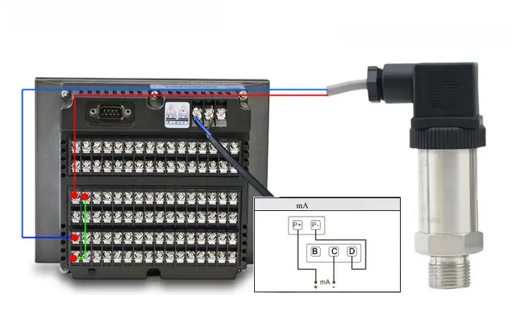
Measure the actual voltage at the transmitter terminals, not at the panel. If you see less than the rated minimum, you found it: undersized supply, too much loop burden, or voltage lost in the wiring. For the wiring side, our 2-wire, 3-wire and 4-wire connection guide walks the terminations, and the 4-20 mA signal calculator converts current to engineering units while you test.
No Output
A dead loop is almost always electrical. Work outward from the power. Confirm 24 V DC is present and the polarity is right; a reversed 2-wire transmitter simply will not power up, and many survive the reversal unharmed once corrected. Then check continuity end to end, the fuse or loop disconnect, and every terminal for a loose or corroded connection. If power and wiring are good and the device is still dark, the transducer electronics may be dead, which a bench test confirms in minutes.
Stuck at 4 mA
An output pinned near the bottom means the device is alive but reads no pressure, or it cannot push current. Three causes cover most cases. Either the applied pressure is genuinely below the range you set, the supply is too weak or the loop burden too high to drive current, or the input is reversed. Apply a known pressure and watch the output. If it does not move, isolate and confirm the pressure actually reaches the diaphragm; a plugged or valved-off impulse line reads exactly like a flatlined sensor. If the device sits at 3.6 mA or below rather than a clean 4 mA, treat it as an NE 43 downscale fault and look for a sensor or wiring fault the device has self-detected.
A damaged or coated process diaphragm is a common cause of drift; for choosing the right wetted form see selecting a flush-mount transducer.
Pegged at 20 mA
A reading driven to the top, and especially to 21 mA or above, points to over-range, an open circuit, or damaged electronics. First rule out a real overpressure: confirm the process is within range with an independent gauge. If the process is fine but the output stays high, check for an open sense line, since an interrupted current loop can latch a connected indicator high. A unit that holds at or above 21 mA after you clear the wiring is reporting an upscale NE 43 fault and is a strong replacement candidate.
Drift: Re-zero or Replace?
This is the call that costs people the most time, because the fix depends on whether the drift is reversible. A small, gradual zero shift, or a reading that tracks ambient temperature, is normally recoverable. Re-zero the transducer with the process vented to atmosphere and verify against a reference; if it holds, you are done. Our calibration walk-through covers the zero-and-span procedure if you need the steps.
If the reading drifts only when the process is hot, the sensor may be past its temperature limit; our high-temperature pressure transducer guide covers the mounting methods that fix it.
What you cannot recover is mechanical damage to the sensing diaphragm. Water hammer or a pressure spike past the overpressure rating can bend the diaphragm past its elastic limit, and once it does it will not return, and you cannot swap the diaphragm on its own. The field signature is specific and worth knowing: slight diaphragm damage stays linear but leaves a small zero offset, so the unit re-zeros cleanly and then walks straight back as service continues. That behaviour is the tell that separates recoverable drift from a dead diaphragm.
| Drift behaviour after re-zero | Likely cause | Action |
|---|---|---|
| Re-zeros and holds | Zero or thermal drift | Recalibrate against a NIST-traceable reference |
| Re-zeros, then walks again | Diaphragm overpressure damage | Replace; calibration will not hold |
| Will not re-zero at all | Failed sensing element or electronics | Replace |
Output Jumps Around
An unstable output has three different causes, and the fix for one will not fix the others, so separate them before you touch anything.
- Real process pulsation. If a pump or fast valve is genuinely shaking the pressure, the transducer is reporting the truth; add a snubber or increase electronic damping rather than blaming the sensor.
- Electrical noise. Long unshielded runs beside VFD or motor cabling couple in interference; bond the cable shield at one end only and route it away from power.
- A loose or wet connection. A terminal backed out, or condensation in a junction box, makes the current flicker as the contact resistance changes. We have opened more than one box on a humid morning to find beaded moisture across the terminals and an output that danced with it.
For the mechanical-versus-electrical split on gauges specifically, the oil pressure gauge fluctuating guide is a useful companion.
Bench-Test the Transducer
When the loop checks out but the reading is steady and wrong, test the device on its own. Power it with the correct excitation, apply no pressure, and read the output. Compare that no-load value to the datasheet zero, ideally against a NIST-traceable reference; a 4-20 mA unit should sit at 4 mA, a ratiometric unit at its specified offset. Then apply a known pressure near full scale and confirm the output matches. A multimeter in series reads loop current directly, and the same instrument verifies excitation voltage at the terminals. If zero and span are both off and will not adjust, the transducer has failed; replace it.
When to Recalibrate vs Replace
Pull the decision together this way, then match the replacement to why the old unit failed.
- Recalibrate when the device re-zeros and holds, zero and span adjust back into tolerance, and nothing in the housing shows physical damage.
- Replace when the diaphragm has seen overpressure or water hammer, when the output latches at an NE 43 fault level after the wiring is clean, or when bench testing shows zero and span that no longer track.
| Finding | Recalibrate | Replace |
|---|---|---|
| Re-zeros and holds, no damage | ✓ | |
| Output sits at 3.6 mA / 21 mA after clean wiring | ✓ | |
| Diaphragm saw water hammer or overpressure | ✓ | |
| Zero and span no longer track on the bench | ✓ |
For steady general service the HM20 general-purpose transducer is well suited, while spike-prone or cycling duty is better served by a more rugged industrial unit such as the HM25. Where you want on-board diagnostics and HART, the HM29 digital transducer flags many of the faults above before they reach the control room. High-temperature service points to the HM26, and sanitary or sticky media to the HM70 flush design. When you are ready to spec a like-for-like swap, our team can match range, connection and material from the pressure transducer range.
Frequently Asked Questions
How can you tell if a pressure transducer is bad?
Power it, apply no pressure, and read the output. If the no-load value is off the datasheet zero and will not adjust, or if zero and span both drift and walk back after re-zeroing, the device has failed. A clean re-zero that holds points to calibration, not a bad transducer.
How do you reset a pressure transducer?
Resetting in the field means re-zeroing. Vent the process to atmosphere, set the zero, then apply a known pressure and trim the span if your model allows it. If it re-zeros and holds, you are done; if it re-zeros and drifts again, the sensing element is damaged.
How do you test a pressure transducer with a multimeter?
Put the meter in series to read loop current, or across the output for a voltage unit. With no pressure applied, compare the reading to the datasheet zero; then apply a known pressure and confirm the output. Use the meter on the terminals to check excitation voltage at the same time.
Is there a typical failure mode for analog pressure transducers?
Yes: overpressure and water hammer damaging the diaphragm, and moisture or loose terminals corrupting the signal. Both show up as drift or instability long before total failure, which is why early diagnosis pays off.
How do you troubleshoot a 2-wire, 3-wire or 4-wire sensor?
Confirm power and polarity first, then loop burden against the 600 Ω-class budget above, then the impulse line, and only then the device. The wiring count changes the terminations, not the diagnostic order.
Replacing a transducer that failed in service?
Tell us the range, process connection, media and what went wrong, and we will return a one-page recommendation with the right HMK pressure transducer for the loop, plus the diagnostic points to hold the new one to.