Impulse Lines for Pressure & DP Transmitters: Field Rules
When a differential pressure transmitter reads a few percent high at low flow, or a level reading jumps the first cold morning of winter, the sensor is usually fine. The impulse line feeding it is not. These small-bore lines carry the process pressure from the tap to the transmitter, and almost every “drifting transmitter” call I take in the field turns out to be a line that traps gas, holds condensate, or freezes. If you get the routing right once, you stop chasing a measurement problem that was never in the instrument. This guide walks the field rules that decide whether your reading is honest.
What Does an Impulse Line Actually Do?
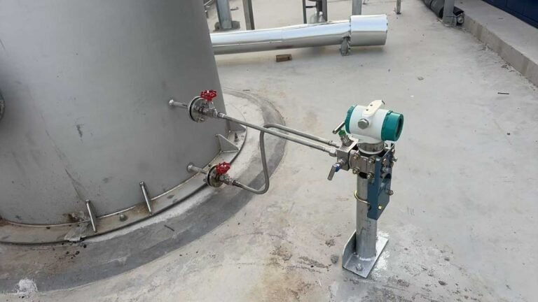
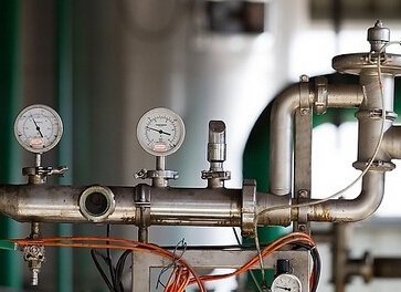
An impulse line is the small pipe or tube that connects a process tap to a pressure, DP, level, or flow transmitter. Its only job is to deliver the true process pressure to the sensor without adding any pressure of its own. The moment a column of trapped gas, settled solids, or frozen liquid sits inside that line, it adds or subtracts head, and the transmitter reports that error as if it were process.
So the design goal is simple to state and easy to get wrong: keep each leg full of one clean phase, all the way from the tap to the cell.
Tapping Points For Liquid, Gas, And Steam
The tap location sets up everything downstream. Tap from the side for liquids so sediment does not drop into the line, from the top for gas so condensate drains back to the process, and from the side with a condensate pot for steam. The transmitter then mounts so each leg self-drains or self-vents toward the process. Use the quick map below before you mark the tap on a drawing.
| Service | Tap on the pipe | Transmitter position | Why |
|---|---|---|---|
| Liquid / hydrostatic level | Side of pipe | Below the tap | Keeps the line liquid-full; sediment stays in the pipe |
| Gas / dry gas | Top of pipe | Above the tap | Condensate drains back; line stays gas-full |
| Steam | Side, with condensate pots | Below the tap | Equal, stable condensate legs on both sides |
For closed-tank level the same logic drives the wet-leg or dry-leg choice, which we cover in the DP level measurement guide.
Slope Direction And Minimum Gradient
Slope is the rule people remember and still reverse on site. Liquid legs slope up from transmitter to tap so gas rises back to the process. Gas legs slope down from transmitter to tap so condensate drains away. The gradient should be continuous, with no flat runs, no U-bends, and no high points where a bubble can park.
Industry practice is at least 1:12, roughly 83 mm per metre; on viscous or dirty service we push that steeper. A single sag that traps one bubble is enough to shift a low-DP reading.
Tube Size Vs Response Time: The Trade-off
Tube bore is a balance, not a maximum. A wider bore resists plugging but slows the response, because more fluid has to move to transmit a pressure change; a narrow bore responds faster but clogs and freezes sooner. Half-inch (12 mm) tubing is the common middle ground for clean service, dropping to 1/4-inch (6 mm) only on clean gas where speed matters.
Keep both legs short and equal in length so they share the same temperature and the same lag. Two legs of different length on a DP cell is one of the quiet reasons a reading wanders when ambient temperature swings.
Match The Tube Material To The Media
Material is where buyers either over-spend or under-protect. Match the tube to the wetted media, not to the cheapest stock on the shelf. The table below is the starting point we use, and we step up a grade whenever chlorides, sour gas, or oxygen service are in play.
| Media | Practical choice | Step up when |
|---|---|---|
| Clean water, air, light hydrocarbons | 316/316L stainless | Chlorides present, move to duplex or Monel |
| Steam, condensate | Carbon steel or 316 | High-purity or cyclic service, use 316 |
| Sour / H2S service | 316L to NACE MR0175 | Higher partial pressure, use duplex |
| Oxygen service | Cleaned-for-oxygen 316 | Always degrease; no hydrocarbon film |
For the tube itself, ASTM A269 sets the dimensions and grades for stainless instrument tubing, while ASME B31.3 covers the pressure rating and wall thickness for the process piping class. Check both before you commit a size on the BOM.
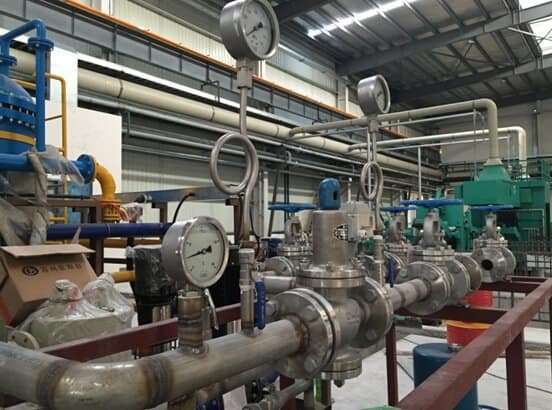
Venting, Draining And Safe Purging
Even a well-sloped line needs vents and drains at the right ends. Put a vent at the high point of a liquid leg and a drain at the low point of a gas leg, and purge through connections near the tap, not through the transmitter. Purging through the cell can slam it with full line pressure and shift the zero or damage the diaphragm. When you purge, run equal flow through both legs so you do not unbalance a DP cell.
| Leg type | Add at | Never |
|---|---|---|
| Liquid leg | Vent at high point | Leave a trapped high spot |
| Gas leg | Drain at low point | Let condensate pool |
| Both (DP) | Purge near taps, equal legs | Purge through the transmitter |
The isolation hardware that makes safe venting possible is the manifold, which we cover in the 2/3/5-valve manifold guide.
Freeze Protection And Temperature Errors
Cold weather turns a working line into a blocked one overnight. Where freezing is possible, you have three honest options: heat-trace and insulate the lines, mount close-coupled so there is almost no line to freeze, or move to a filled system that has no water leg at all. Heat tracing is the usual answer outdoors, but it has to cover the full run including the manifold, because the cell sees the coldest point.
The same temperature thinking applies even above freezing: keep both legs at the same temperature, since a warm leg and a cold leg hold fluid at different densities and that difference shows up as a false DP.
Put A Number On The Piping Error
This is the part most guides skip, so here are the numbers. The error from a liquid column is just density times gravity times height. One metre of trapped water on one leg of a DP cell adds about 9.81 kPa of false differential (1000 kg/m³ x 9.81 m/s² x 1 m). A 0.5 m gas pocket in a water leg removes roughly 4.9 kPa. On a cell ranged for 25 kPa, that half-metre bubble is a 20% error with no fault in the transmitter at all.
A frozen or fully plugged line is worse than an offset: the signal stops tracking and simply locks at the last value. I have seen this same failure on gas-flow loops in the field, and a documented case on a 1,880 m³ blast-furnace gas-flow loop captures it exactly: the furnace gas was not fully dried, water settled at the orifice high-pressure tap and ran down the positive impulse leg, the two legs ended up holding unequal liquid columns, and the DP transmitter read flow high with nothing wrong in the cell.
Run the check yourself: multiply any suspected unequal column (in metres) by 9.81 to see, in kPa, how much zero error it explains before you recalibrate anything.
Spotting A Plugged Or Blocked Line
A plugging line rarely fails cleanly; it fades. The signal gets sluggish, responds late to a real step change, and a DP reading drifts as one side restricts before the other. The field test is direct: crack the manifold drain or equalize and watch whether the reading reacts the way a clear line should. The ISA troubleshooting guidance for gauges and impulse lines walks the same symptom-first sequence we use on site.
Modern smart DP transmitters add a second layer here by watching the statistical noise of the pressure signal, which flattens as a line plugs, and flagging it before the reading is visibly wrong. That diagnostic is one reason we point customers on critical or remote duty toward a smart unit such as the HM3051 smart DP transmitter rather than a basic analog cell.
Impulse Lines, Flush Mount, Or Remote Seal?
Sometimes the right impulse line is no impulse line. If the media is hot, viscous, slurry-like, crystallizing, or has to stay sanitary, a water or fill leg will plug, freeze, or breed bacteria no matter how well you slope it. In those cases mount the sensor at the process with a flush diaphragm, or use a remote diaphragm seal with a filled capillary, so nothing sits in a dead leg.
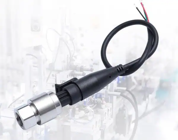
For sticky and high-temperature duty we move to a flush-mount pressure transducer or a high-temperature unit like the HM26; for general DP service the DP transmitter range covers the standard impulse-line installs. The decision is simple: if you cannot keep the leg clean and one phase, take the leg away.
If you are repiping a problem loop, start with one change: fix the slope direction and equalize leg length, then recheck the zero before you touch the calibration. That single step clears more “bad transmitters” than any other.
The transmitters we reach for on these installs:
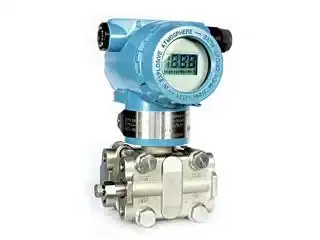
HM3051 Smart DP Transmitter
HART smart cell with plugged-line diagnostics for critical DP loops.
View Specs →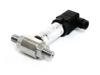
HM31 DP Transmitter
Workhorse differential pressure transmitter for flow, level and filter DP.
View Specs →
HM26 High-Temp Transmitter
Ceramic capacitive cell for hot service where a fill leg cannot survive.
View Specs →Frequently Asked Questions
What slope should impulse tubing have?
At least 1:12, about 83 mm per metre, continuous and in one direction. Liquid legs slope up toward the tap; gas legs slope down toward the tap. Steeper is better on dirty or viscous service.
Why is my DP transmitter reading not zero at no flow?
The most common cause is unequal fluid columns in the two legs, usually a trapped gas pocket or condensate on one side. One metre of column difference is about 9.81 kPa of false offset, so check and equalize the legs before recalibrating.
How long can impulse lines be?
Keep them as short as possible. Longer lines slow the response and raise the chance of trapped gas or sediment. If a long run is unavoidable, use a remote seal with a capillary or mount the transmitter closer to the tap.
Do both impulse lines need to be the same length?
Yes, for a DP cell. Equal length and equal routing keep both legs at the same temperature and lag, which prevents density-difference and response errors that look like real DP.
How do I tell if an impulse line is plugged?
Watch for a sluggish or drifting signal that lags real changes. Crack the manifold drain or equalize and see if the reading reacts normally. A smart DP transmitter can flag a plugging line from the drop in signal noise before it is visibly wrong.
When should I use a remote seal instead of impulse lines?
When the media is hot, viscous, crystallizing, slurry, or sanitary, and a fill or water leg would plug, freeze, or contaminate. A flush diaphragm or remote seal with capillary removes the dead leg entirely.
Need help speccing a DP transmitter or its piping?
Our application engineers can review your impulse-line layout and recommend the right transmitter for the service.
Request a Quote Browse DP Transmitters