4-20 mA Current Loop: How the Signal Works
If you are wiring a pressure or temperature transmitter into a control system, the signal it sends is almost always a 4-20 mA current loop. It is the most common analog standard in process plants. Understanding why it uses current, not voltage, tells you why it survives the long cable runs and electrical noise that would corrupt a voltage signal.
This guide covers the fundamentals: what the loop is, why 4 mA is the zero point, how two wires both power the device and carry the reading, how to size the loop supply, and how to convert milliamps back into pressure or temperature.
What Is a 4-20 mA Current Loop?
A 4-20 mA loop is an analog signal in which the measured value is represented by a current between 4 and 20 milliamps. The transmitter sets 4 mA at the bottom of its range and 20 mA at the top, so a reading at mid-span sends 12 mA. Every device in the series circuit sees the same current, because current is constant around a single loop, and that single fact is the reason the standard has lasted for decades.
The loop has three parts. A DC power supply, usually 24 V, drives the circuit. The transmitter acts as a variable current regulator, setting how much current flows. A receiver senses the current, often across a precision 250 Ω resistor that turns 4-20 mA into a 1-5 V input for the controller. The range is defined by ISA-50.00.01 and IEC 60381-1:1982, which standardize the same 4-20 mA signal across instrument makers. You will also see the signal carry digital data on top of it, which the HART vs 4-20 mA comparison covers, and you can weigh it against other output types in the pressure transmitter output signals guide.
Why Does the Loop Use Current Instead of Voltage?
This is the question that explains everything else. In a series loop the current is identical at every point, so it does not matter how much resistance the cable adds; the 12 mA leaving the transmitter is the 12 mA arriving at the controller. A voltage signal does not behave that way, because wire resistance drops part of the voltage before it reaches the receiver.
Consider a 500 m cable run of 1.0 mm² copper, which has a loop resistance near 18 Ω. A 4-20 mA signal is completely unaffected by that resistance, so the reading stays accurate. A 0-10 V signal driving the same line would lose voltage across it, and the error grows with distance and load. In the field on long pumping-station and tank-farm runs, we have seen a current loop hold its reading where a voltage line lost several percent over the same cable. That immunity is why 4-20 mA is best suited to field instruments that sit hundreds of meters from the control room, and why we specify it as the default output on our transmitters.
Live Zero: How 4 mA Catches a Broken Wire
The choice of 4 mA, rather than 0 mA, for the zero point is deliberate, and it is one of the most useful features of the standard. Because a healthy loop never drops below 4 mA, a reading of 0 mA can only mean a fault: a broken wire, a dead transmitter, or a lost supply. This is called live zero, and it lets the control system tell the difference between a true zero reading and a failed signal.
The idea extends to fault detection at both ends of the scale. Under the NAMUR NE43 recommendation, a transmitter that detects an internal failure drives the current to a defined alarm level. That level is typically at or below 3.6 mA for a downscale alarm, or at or above 21.0 mA for an upscale alarm. You should decide the alarm direction during design: downscale suits a process where a low reading is the safe state, while upscale suits the opposite. Either way, the diagnostic comes free with the signal.
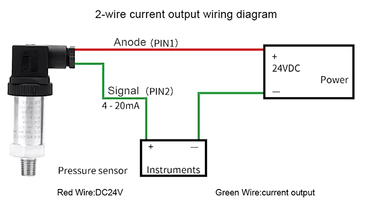
How Two Wires Both Power and Read the Transmitter
Most field transmitters are loop-powered, which means the same two wires that carry the signal also deliver power to the device. There is no separate supply cable. The transmitter draws its operating current from the loop and never lets the total fall below 4 mA, so even at the bottom of its range it has enough current to run its own electronics.
This two-wire arrangement is ideal for plant wiring because it halves the cable count and simplifies installation. It does set a design limit: the transmitter must operate on the current available within the 4-20 mA budget, which is why loop-powered devices are efficient by design. For the practical side of landing those two wires, see the 4-20 mA pressure transmitter wiring guide, and for how the sensor produces the value in the first place, the pressure transmitter working principle.
How Do You Size the Loop Supply and Resistance?
A loop only works if the supply voltage can push 20 mA through all the resistance in the circuit. The total resistance includes the cable, the sense resistor, and any barriers or indicators in series. The maximum resistance the loop can tolerate follows a simple rule.
Maximum loop resistance equals the supply voltage minus the transmitter’s minimum operating voltage, divided by 0.020 A. With a 24 V supply and a transmitter that needs at least 12 V to operate, the loop can carry up to (24 − 12) ÷ 0.020 = 600 Ω. A 250 Ω sense resistor plus a few ohms of cable sits comfortably inside that budget, but add several series indicators or a long run and you can exceed it, at which point the signal clips before it reaches 20 mA. Our 4-20 mA loop resistance calculator works the budget for you.
Converting Between Milliamps and Engineering Units
To read the loop, you convert the current back into the measured value using the transmitter’s calibrated range. The relationship is linear between the lower range value and the upper range value, so the math is the same for pressure, temperature, or level.
| Current | Percent of span | Reading on a 0-10 bar range |
|---|---|---|
| 4 mA | 0 % | 0 bar |
| 8 mA | 25 % | 2.5 bar |
| 12 mA | 50 % | 5 bar |
| 16 mA | 75 % | 7.5 bar |
| 20 mA | 100 % | 10 bar |
The value equals the lower range value plus the fraction of the span the current represents, or LRV + (mA − 4) ÷ 16 × (URV − LRV). For a transmitter ranged 0 to 10 bar, a 12 mA reading is 0 + (12 − 4) ÷ 16 × 10 = 5 bar, exactly mid-span. To go the other way, milliamps equal 4 + 16 × (value − LRV) ÷ (URV − LRV). Our 4-20 mA calculator handles both directions when you need a quick check.
Where 4-20 mA Fits, and Where It Doesn’t
The 4-20 mA loop is best suited to carrying one analog variable reliably over distance, and for that job it remains the safe default across process industries. It is simple, noise-immune, self-powering, and self-diagnosing, which is why it is the output we fit on most pressure and temperature transmitters.
Its limit is that a plain loop carries only one value and no digital detail. Where you need multiple variables, remote configuration, or device diagnostics, a digital layer such as HART rides on the same wires, or a fieldbus replaces the loop entirely. For most measurements, though, the trade-offs still favor the current loop: choose 4-20 mA when you want a dependable single-variable signal, and add HART on top when you also want to configure and interrogate the device without extra wiring.
- Single analog variable over distance: choose 4-20 mA for noise immunity and live-zero fault detection.
- Long cable runs from field to control room: the current loop is ideal, because cable resistance does not change the reading.
- Configuration or diagnostics needed: keep 4-20 mA and add HART on the same wires.
- Loop design: size the supply so maximum loop resistance, (V_supply − V_min) ÷ 0.020, exceeds cable plus sense resistor.
- Reading the signal: value = LRV + (mA − 4) ÷ 16 × (URV − LRV); 12 mA is always mid-span.
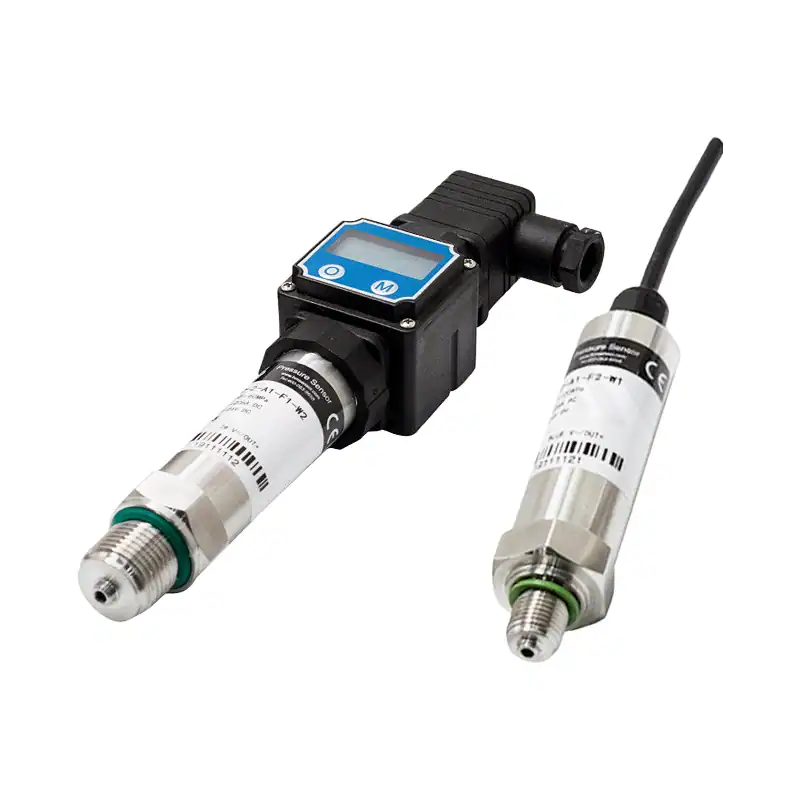
HM20 Pressure Transmitter
General-purpose two-wire transmitter with a loop-powered 4-20 mA output for process pressure.
View Specs →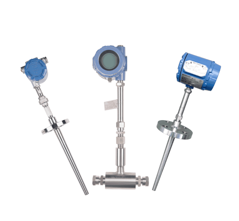
SBW Temperature Transmitter
Head-mount transmitter that converts RTD or thermocouple input to a linearized 4-20 mA loop.
View Specs →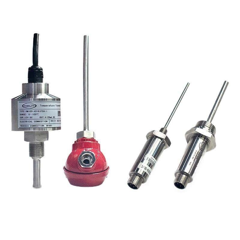
HM100 Temperature Transmitter
Universal-input transmitter with 4-20 mA and HART, for field or DIN-rail temperature loops.
View Specs →Spec a 4-20 mA transmitter with our engineers
Send your measurement, range, and loop layout. We will return a transmitter, output option, and a loop-power check for the run.
Request a QuoteFrequently Asked Questions
What does 4-20 mA mean?
It is an analog signal where 4 mA represents the bottom of the transmitter’s range and 20 mA the top, so 12 mA is mid-span. The same current flows around the whole series loop.
Why does the loop start at 4 mA and not 0?
The 4 mA floor is a live zero. Because a healthy loop never reads below 4 mA, a 0 mA reading can only mean a broken wire or a failed device, which lets the control system detect faults.
Does cable resistance affect a 4-20 mA reading?
No. Current is constant everywhere in a series loop, so cable resistance does not change the reading. A voltage signal would lose accuracy over long cable runs as wire resistance drops part of the voltage.
What supply voltage does a 4-20 mA loop need?
Commonly 24 V DC. The supply must overcome all loop resistance at 20 mA. Maximum loop resistance equals the supply voltage minus the transmitter’s minimum voltage, divided by 0.020 A.
How do you convert 4-20 mA to a reading?
Use value = LRV + (mA − 4) ÷ 16 × (URV − LRV). For a 0-10 bar range, 12 mA gives 5 bar. The relationship is linear across the calibrated span.
What is NAMUR NE43?
A recommendation that sets fault current levels outside the 4-20 mA band, typically 3.6 mA or below for a downscale alarm and 21.0 mA or above for upscale, so a failed transmitter signals its fault rather than reading a plausible value.