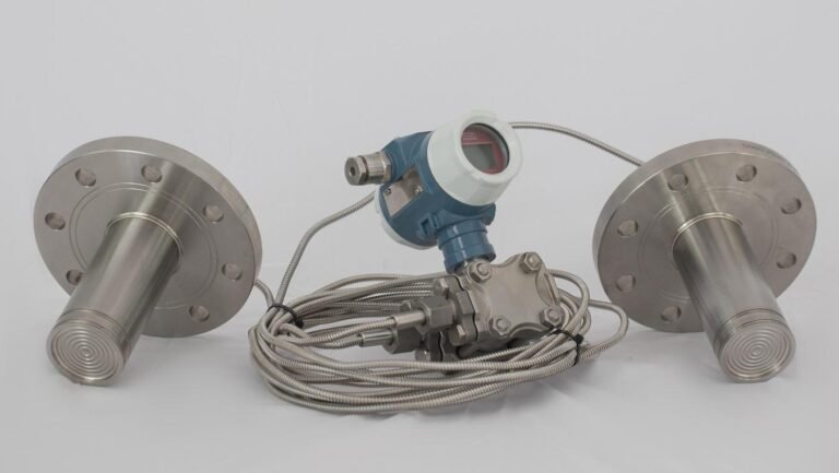
Differential Pressure Transmitter for Flow Measurement
A differential pressure transmitter is still the flow meter you will find on more lines than any other, and not because it is the most accurate. It is cheap, it is hard to kill, and it works on almost any clean fluid. The catch is that the transmitter does not measure flow at all. A primary element such as an orifice plate makes a pressure drop, and the transmitter reads that drop. Whether your flow loop is accurate or useless comes down to how you size and apply that transmitter, and that is what you are choosing here.
Related: impulse-line piping decides your flow accuracy — see impulse lines for pressure & DP transmitters for slope, tube size, and freeze rules.
If you have already decided to measure flow with differential pressure, this guide is for you: what range to set, how much turndown is safe, why the reading falls apart at low flow, and how to pipe it so the number on the screen is real. Where the maths matters, the companion orifice plate sizing calculator and DP flow calculator do the arithmetic for you.
How a DP transmitter measures flow
When fluid passes through a restriction it speeds up, and its pressure falls. Bernoulli’s principle ties the two together: the pressure drop across the element rises with the square of flow, so the differential is proportional to flow squared. Turn that around and flow is proportional to the square root of the differential. That single square root is the source of every strength and every weakness you will meet in DP flow. Your transmitter’s one job is to read the differential precisely. Converting it to flow is then done either inside a smart transmitter or by the control system, and the DP flow calculator shows you the percent-DP to percent-flow relationship behind it.
How do you size the transmitter range and turndown?
Start from the primary element, not from the transmitter. The element is sized to make a chosen full-scale differential at maximum flow, commonly 25 kPa, about 100 inH₂O, though you will see anything from a few kPa to 100 kPa. That full-scale differential is your calibrated span: zero at the bottom, the element’s full-flow differential at the top. The mistake to avoid is buying one high-range cell and turning it down hard. A transmitter’s accuracy is quoted against its maximum span, so a large turndown multiplies the error you actually get in flow units.
| Element full-scale ΔP | Sensible transmitter cell | Turndown | Comment |
|---|---|---|---|
| 25 kPa | 0 to 100 kPa range | 4:1 | Comfortable, good accuracy headroom |
| 10 kPa | 0 to 100 kPa range | 10:1 | Acceptable on a high-accuracy cell only |
| 6 kPa | low-range, 0 to 10 kPa cell | under 2:1 | Prefer a low-range cell over a hard turndown |
You should keep the DP turndown in single digits unless the cell is a high-accuracy model rated for more. If the full-scale differential is small, the right answer is a low-range transmitter, not an aggressive turndown of a general-purpose one. To get the differential your element will actually make for a given flow and pipe, the orifice plate sizing calculator returns it directly, along with the permanent pressure loss.
Why is DP flow accuracy poor at low flow?
The square root that makes DP flow possible also caps its turndown. Because differential falls with the square of flow, half flow gives you only a quarter of the differential, and 10% flow gives you just 1% of it. A fixed transmitter error, say 0.1% of span, is therefore a tiny slice of the differential at full flow but a large slice of it near the bottom. The flow error grows accordingly.
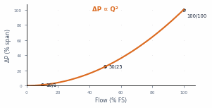
| Flow (% FS) | ΔP (% of span) | Flow error from a 0.1% span cell |
|---|---|---|
| 100% | 100% | 0.05% |
| 50% | 25% | 0.2% |
| 32% | 10% | 0.5% |
| 10% | 1% | 5% |
Two practical things follow. First, your useful flow turndown is the square root of the DP turndown, so a 10:1 differential range buys only about 3:1 in flow. Second, you should set a low-flow cut-off, usually around 5 to 10% of full-scale flow, below which the transmitter forces flow to zero. Without it, square-root amplification turns sensor noise into wild totalised readings when the line is nearly still. Every smart transmitter offers this cut-off, and you should switch it on.
Installation that makes or breaks the reading
I will be honest about where the trouble usually is. Most of the DP flow loops I am called out to fix are not failing transmitters at all. The impulse legs are unbalanced, or the square root is being taken twice. The two pressure taps reach the cell through impulse lines, and any density difference or trapped phase between them shows up as a false differential, so we treat the piping as part of the instrument.
Three rules carry most of the benefit. Slope the impulse lines continuously, at least 1 in 12, so the unwanted phase drains back to the process: downward on liquid and condensable service so gas rises away, upward on dry gas so condensate runs back. Keep both legs identical in length, temperature and fill so they stay balanced. Use the right manifold: a 3-valve manifold, two isolate and one equalise, is enough to zero and isolate the cell, while a 5-valve manifold adds vent and test valves so you can calibrate without breaking containment, which is why you will see it as standard on steam and hazardous service.
Service also sets your wet or dry leg arrangement. On clean liquid both legs fill with process liquid. On gas you keep both legs dry and self-draining. On steam, condensate pots let both legs fill with condensate to a known, equal level. I have seen the same fault on more than one steam line, where both legs were piped but one filled before the other, and the zero stayed offset until we levelled them. For hot, viscous, crystallising or corrosive media, remote diaphragm seals with capillaries move the wet part out to the process connection and keep the cell clean. Balance the legs and get the manifold right, and your transmitter has a fair chance. Get them wrong and no amount of transmitter accuracy will save the measurement.
Which primary element feeds the transmitter?
The transmitter is the same workhorse whichever element you pick. What changes is the differential it sees and the permanent pressure loss your plant pays for the life of the line.
| Element | Permanent loss | Best suited to |
|---|---|---|
| Orifice plate | High, about 60 to 85% of ΔP | Clean fluids, lowest cost, most common |
| Venturi | Low, about 10 to 15% | Large lines, energy-sensitive, dirtier fluids |
| Flow nozzle | Medium | High-velocity, high-temperature steam |
| Averaging pitot | Very low | Large ducts, retrofit, low available ΔP |
For a concentric orifice, the default choice, the orifice plate sizing calculator solves the bore and beta ratio to ISO 5167:2022 and reports both the permanent pressure loss and the transmitter range to match it.
Smart or analog: where do you take the square root?
A modern smart transmitter can take the square root internally and output a signal already linear in flow, with the low-flow cut-off and engineering units set over HART. The alternative is to output a linear differential, 4 to 20 mA proportional to DP, and let the DCS or PLC take the root. Either way works, and the only rule that matters is that the root is taken once. A bug we see at commissioning is double extraction, with the transmitter set to square root and the DCS block also extracting. The indicated flow then looks plausible at mid-scale and goes badly wrong at the ends. Decide where the root is taken, write it down, and verify it during loop checks. Transmitter performance under these conditions is defined in IEC 60770:2010.
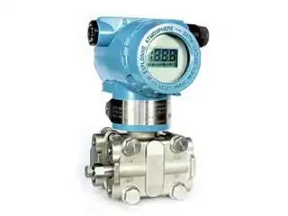
Choosing your HMK DP transmitter
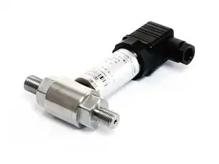
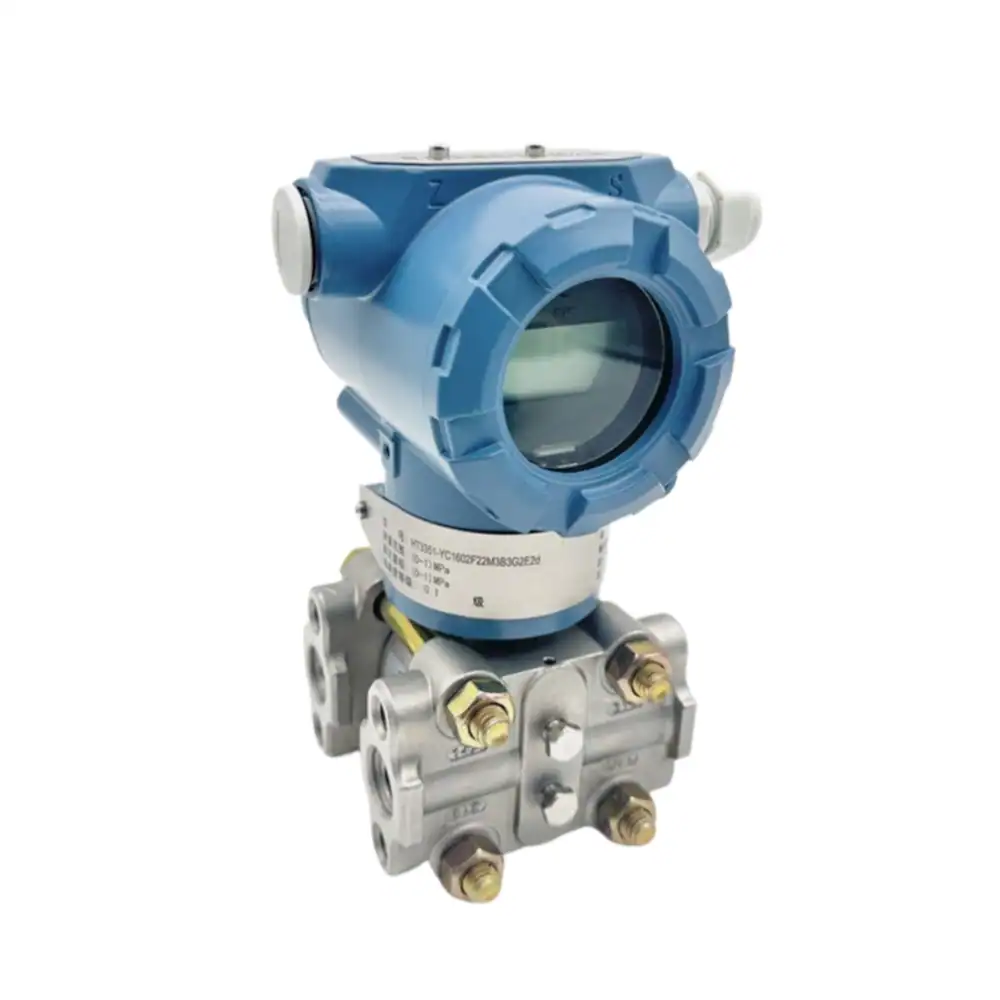
For orifice and other DP flow service, three HMK transmitters cover most of what you will specify. The HM3051 is the smart, HART-capable choice: a capacitive cell at 0.1% accuracy with digital re-ranging and square-root extraction, well suited to loops that need turndown and configuration. The HM31 uses a monocrystalline-silicon cell, covers spans from 0 to 10 kPa up to 2 MPa with a 20 MPa static rating at 0.1%, and handles both flow and level. The HM1151 is the rugged classic-form capacitive cell at 0.25% with generous overload protection for harder service. Match the cell range to the element’s full-scale differential, keep the turndown modest, and set the low-flow cut-off.
Frequently asked questions
Can a differential pressure transmitter measure flow?
Yes. Paired with a primary element such as an orifice plate, venturi or averaging pitot, the transmitter reads the pressure drop the element makes, and flow is proportional to the square root of that differential. The transmitter or the control system extracts the square root to give you flow. It is the most common flow method for clean, low-viscosity liquids, gases and steam.
How do you choose the DP transmitter range for flow?
Set the calibrated span equal to the element’s full-scale differential, zero to the differential at maximum flow. Pick a cell whose maximum span covers it without a hard turndown, since single-digit turndown keeps your accuracy in flow units. If the differential is small, use a low-range cell rather than turning a high-range one down.
Why is DP flow accuracy poor at low flow?
Because differential falls with the square of flow, at 10% flow the DP is only 1% of span, so a fixed transmitter error becomes a large share of the actual reading. Your useful flow turndown is the square root of the DP turndown, and you set a low-flow cut-off, around 5 to 10%, to suppress meaningless readings near zero.
Do you need a 3-valve or 5-valve manifold?
A 3-valve manifold is enough to isolate and zero the cell on ordinary service. Choose a 5-valve manifold when you need to vent and test for calibration without breaking containment, which is the usual choice on steam and hazardous duty.
Should the square root be taken in the transmitter or the DCS?
Either is fine, as long as it is taken once. If your smart transmitter outputs a linear-in-flow signal, leave the DCS block on linear. If the transmitter outputs linear differential, let the DCS extract. Confirm which during loop checks so you never extract twice.
Specifying a DP transmitter for a flow loop?
Tell us the fluid, line size and the element’s full-scale differential, and we will confirm the range, turndown and HMK model for the job.