Hydraulic Pressure Transducer Selection: Surviving Spikes and Fatigue
If you are specifying a pressure transducer for a hydraulic system, the hard part is rarely the working pressure. It is everything the system does around that pressure: the spikes when a valve slams shut, and the millions of cycles a press or a power unit runs every year. This guide walks you through how to choose a unit that survives both, so the transducer you put on the line is still reading true a year later.
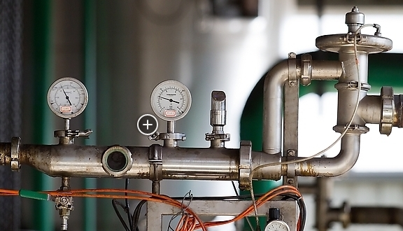
When the spikes come from a pump or valve rather than the sensor itself, a pressure snubber ahead of the gauge is often the cheaper first fix.
Integrating a transducer into your own equipment rather than a field line? See our OEM pressure transducer spec and sourcing guide.
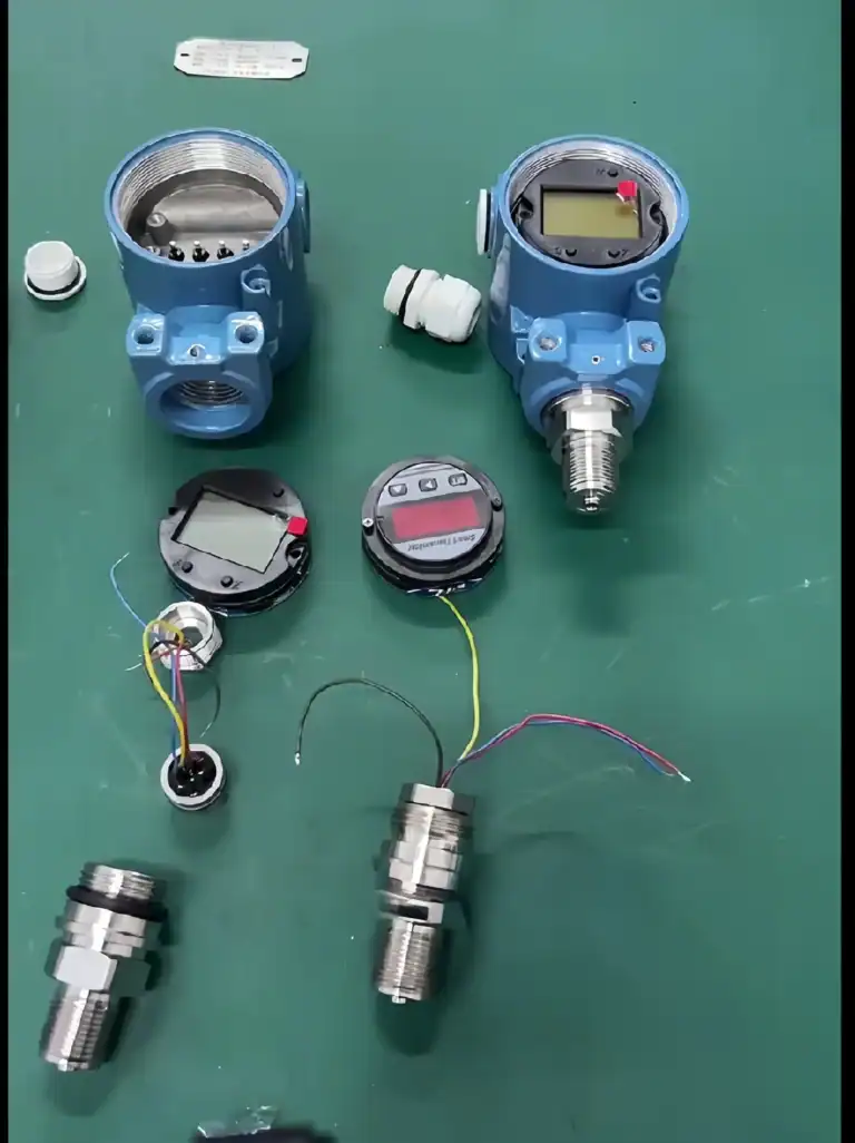
What makes a hydraulic pressure transducer different?
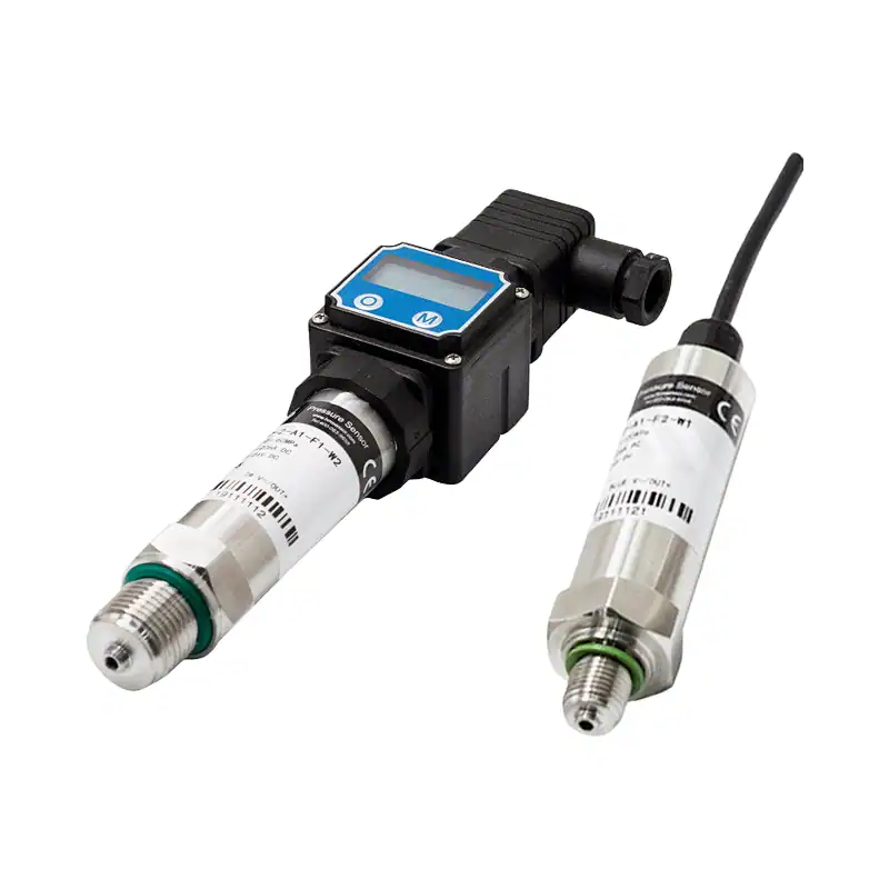
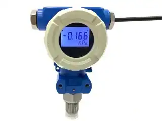
A hydraulic pressure transducer works on the same principle as any pressure transmitter. A sensing element flexes under pressure, a circuit conditions that signal, and the unit outputs 4-20 mA, 0-5 V, or a digital value that your PLC or display reads as pressure.
A hydraulic-duty unit is built with more margin than a general process transmitter. The two may share a sensing element, yet the hydraulic version carries a higher overpressure rating, a longer fatigue life, and a sturdier port. When we help a customer spec a unit for a power pack or a cylinder line, we look at those survival numbers first and the headline accuracy second. If you want the wider map of output and signal options before you narrow down, our guide to pressure transmitter types covers it.
Why do hydraulic systems destroy ordinary sensors?
Two things wear hydraulic sensors out, and you should size for both.
The first is the pressure spike. When a directional valve closes quickly or a pump pulses, the moving column of oil has nowhere to go, and pressure surges for a few milliseconds. The surge follows the water-hammer relation, so it scales with the fluid density, the wave speed in the line, and how fast the flow stops. A published worked example shows the scale: in a DN250 steel line the pressure wave travels near 1,243 m/s, so closing a valve on a 2 m/s flow adds roughly 25 bar on top of the working pressure, and the figure climbs with faster flow and stiffer pipe. On a lower-pressure line, that transient can reach several times the working value, which is why a unit sized only to the gauge reading tends not to last.
The second is fatigue. A machine that cycles every few seconds asks the diaphragm to flex tens of millions of times a year. A sensing element that creeps or work-hardens will drift long before it ever cracks. In the field on hydraulic power units, we see this surge-and-cycle pair, rather than the steady setting, do most of the damage to a transducer’s zero.
Which sensing technology should you choose?
Choose the sensing element by how many pressure cycles it will see, not by the catalog accuracy figure alone. Three technologies cover almost every hydraulic job.
| Sensing technology | Fatigue / creep | Overpressure headroom | Typical max range | Best hydraulic duty |
|---|---|---|---|---|
| Diffused-silicon (piezoresistive) | Some long-term drift under heavy cycling | Moderate | To ~100 MPa (HM25) | Mobile and general plant, steady to moderate cycling |
| Sapphire-on-silicon (HM28) | None — no fatigue, no creep | High | To 260 MPa | High pressure and high cycle count (presses, injection) |
| Thin-film | Low | High | Very high static | Very high static pressure |
Diffused-silicon (piezoresistive) sensors are the default choice, and for ordinary mobile or industrial duty they are usually all you need. They are accurate and affordable, and their limit shows up only under relentless high-pressure cycling, where long-term drift and overpressure headroom decide service life. Our industrial pressure transmitter uses a piezoresistive silicon sensor with HART and ±0.1% FS to 100 MPa, which suits most plant hydraulics.
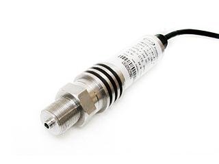
Sapphire-on-silicon (SOS) is the better choice when the duty is severe. The HM28 we ship uses a mono-crystalline silicon-sapphire element on a titanium diaphragm, and one datasheet property decides it for hydraulics: no fatigue and no creep, with zero hysteresis, rated to 260 MPa across media from −65 to +200 °C at ±0.1% FS. On a press or an injection machine that cycles all day, that “no fatigue” property is worth more to you than a tenth of a percent of accuracy.
Thin-film sensors sit between the two for very high static pressure. For cyclic hydraulic work, though, we keep coming back to SOS once the pressure or the cycle count climbs.
The specs that decide whether it survives
Size the range and the overpressure rating to the worst spike, then confirm the proof and burst numbers. Five lines on the datasheet usually decide the outcome.
Range comes first, and the common trap is sizing it to the gauge reading. If a system runs at 21 MPa but spikes well above that, a 25 MPa transducer will live a short life, so you should leave headroom for the transient. The overpressure (proof) rating is the pressure the unit takes without a permanent shift, and burst is where it ruptures; both should clear your spike with margin. Response time matters when you actually need to see the spike rather than ride through it. Accuracy is real, yet in hydraulics it should rank behind survival, so ±0.25% FS is fine for most monitoring and ±0.1% FS for control. Sealing and electrical ruggedness close the list: an IEC 60529:1989 IP65 or IP67 housing and proper surge handling keep wash-down and electrical noise out. ISO 4413:2010 sets the wider safety and sizing rules for the system the transducer plugs into, and it is a useful cross-check on the ratings you choose.
Matching the transducer to your application
Mobile equipment, presses, and test stands each fail differently, so you should size them differently.
On mobile and light industrial equipment, the pressures are moderate and the cycling is real but not extreme. A rugged general-purpose unit is usually the best fit here. Our general-purpose pressure transmitter covers ranges to 100 MPa at ±0.25% FS with 4-20 mA, 0-5 V, or HART and IP65/IP67 sealing, and a snubber takes care of the spikes.
On presses and injection-molding machines, the pressure is high and the cycle count runs into the millions, so sapphire is worth it here. We would spec the HM28 here because the no-fatigue, no-creep element holds its zero through years of cycling at pressures up to 260 MPa, where a standard silicon unit may drift.
On test stands and R&D rigs, the spike or the water-hammer event is often the measurement you actually want. A fast dynamic unit like our dynamic pressure transmitter captures the transient instead of averaging it away, and for the high static-pressure plumbing around the rig the HM25 gives you a HART signal at ±0.1% FS.
| Application | Typical pressure / cycling | What to prioritize | HMK model |
|---|---|---|---|
| Mobile & light industrial | Moderate pressure, real but not extreme cycling | Ruggedness, sealing, a snubber | HM20 / HM25 |
| Press & injection molding | High pressure, millions of cycles | No-fatigue sapphire element | HM28 |
| Test stand & R&D | Fast transients, water hammer | Fast dynamic response | HM90 (+ HM25 static) |
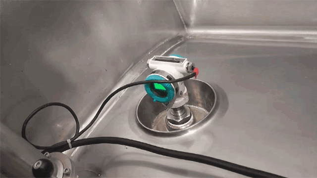
Installation and protection
Many early hydraulic-sensor failures are an installation problem rather than a sensor problem, so it is worth starting with a snubber. A pressure snubber or a small orifice damps the spike before it reaches the diaphragm, and on any line with fast valve action you should treat it as standard rather than optional. Mount the transducer where it sees pressure but not the worst of the pump’s mechanical vibration, keep the port clean, and avoid trapping air that turns a smooth reading into a noisy one. Good loop wiring helps too; our 4-20 mA wiring guide covers that side.
How do you test a hydraulic transducer in the field?
Before you replace a transducer you think is faulty, it is worth proving it with a short field check. Compare its reading against a reference gauge or a dead-weight tester traceable to NIST at several points across the range, not just at zero. Check the zero and span at the operating temperature, because a unit that reads true cold can shift once the oil heats up. After a known spike event, look for a zero shift, which is the classic sign of an overpressure hit. If the zero has walked and will not return, the element has taken damage and the unit is done. Our calibration walkthrough covers the comparison method in more detail.
A simple rule for choosing
The rule is simple: set the range and overpressure to the worst spike, then pick the sensing technology by cycle count. For steady or low-cycle service, a diffused-silicon unit such as the HM20 or HM25 is usually ideal. For high pressure or millions of cycles, the sapphire HM28 is the safer choice. When the transient itself is the data, add the HM90. And on any line with fast valve action, fit a snubber.
Need help matching a transducer to your hydraulic duty? Send us your working pressure and cycle rate.
Request a Quote Browse Pressure TransmittersFrequently Asked Questions
What is a hydraulic pressure transducer?
It is a pressure transmitter built for hydraulic service. It senses oil pressure at a port and outputs 4-20 mA, 0-5 V, or a digital signal, with the overpressure and fatigue margins a hydraulic line demands.
How does a hydraulic pressure transducer work?
A sensing element flexes under pressure, a circuit conditions the signal, and the unit outputs a proportional 4-20 mA current or voltage that your PLC or display reads as pressure.
How do I test a hydraulic pressure transducer in the field?
Compare it against a reference gauge or a dead-weight tester at several points, check zero and span at the operating temperature, and look for a zero shift after any spike event, which points to overpressure damage.
What pressure range and overpressure rating do I need?
Size both to the worst spike, not the working pressure. A valve closing on a moving oil column adds a water-hammer surge that scales with flow speed, and on lower-pressure lines it can reach several times the working value, so leave headroom and confirm the proof and burst ratings clear that transient.
Why do hydraulic pressure transducers fail early?
The two usual causes are pressure spikes that exceed the overpressure rating and cyclic fatigue that drifts the element. A fatigue-free sapphire element like the HM28 and a snubber on spike-prone lines remove most early failures.
Related: On hot hydraulic and thermal-oil lines the fluid can exceed the sensor rating, so see the high-temperature pressure transducer guide for the 250°F to 2192°F methods.