OEM Pressure Transducer: How to Spec and Source One
When you build a pressure measurement into your own equipment, the hard part is rarely the accuracy number. It is matching the output to your controller. It is leaving overload margin for your worst spike. And it is getting a part you can buy in volume with the port and connector you need.
Get any one wrong and the symptom looks the same on the bench: the board reads nothing, or the sensor dies early in the field. This guide walks the OEM decisions in the order they matter, with real figures from sensors we build, so you can fill a request for quote with confidence.
What changes when the transducer goes inside your product
An OEM pressure transducer is specified differently from a field transmitter you bolt onto a pipe. You integrate a sensing element, or a compact packaged sensor, onto your own board and supply rail. That shifts the priorities. Board space and unit cost move up the list. The output usually has to talk to a microcontroller ADC, not a PLC analog card.
Batch-to-batch consistency matters more than any single unit, because your line cannot stop to recalibrate every device. And you often want to lock one configuration, then reorder the same part for years. So the right starting point is not “how accurate.” It is “how does this connect, survive, and ship.” We will take those in turn.
Output type is the first real decision
The output dictates how you wire the sensor, how far the signal runs, and how much analog-to-digital work your board does. Pick it before anything else, because it constrains every later choice.
| Output | Best suited for | Watch out for |
|---|---|---|
| Ratiometric 0.5–4.5 V | Short runs to a 5 V MCU ADC; lowest-cost integration | Output tracks supply, so the 5 V rail must be clean and shared with the ADC reference |
| Amplified 0–5 V / 1–5 V | General board use; 1–5 V gives a live-zero to detect open circuits | Needs a stable regulated supply; not ideal over long cable |
| 4–20 mA | Runs of several metres; electrically noisy machines | Two extra components and more current draw; overkill on a short trace |
| mV/V (unamplified) | You already have a precision instrumentation amp and want full calibration control | No onboard conditioning, so noise and temperature handling fall to you |
| Digital (I²C / SPI / UART) | Direct register read, multi-sensor buses, no ADC error budget | Bus length is limited; firmware effort to integrate |
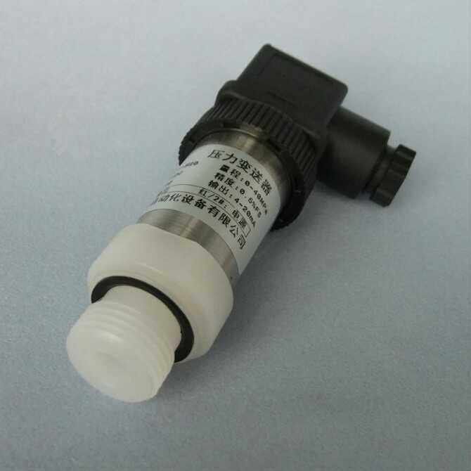
For most board-level designs, a ratiometric 0.5–4.5 V output is the path of least resistance. It is why our HM12-UC1 ships that way as standard, with a 500 ±100 mV zero and a 4500 ±100 mV full scale off a 5 VDC supply. The catch is in the name. A ratiometric output is referenced to the supply, so a sagging or noisy 5 V rail moves the reading with it. Tie the sensor supply to the same reference your ADC uses, and that error cancels (see this ratiometric measurement primer).
If you would rather skip the ADC, the digital variant of the same family, the HM12-UC7, adds a UART/SPI interface with 24-bit pressure resolution, so the microcontroller reads a calibrated value directly. When the sensor sits a few metres from the electronics on a noisy machine, step up to 4–20 mA and accept the extra parts. For a deeper look at signal types, see our guide to pressure transmitter output signals.
Sizing range and overload for OEM duty
Two ranges matter, and they are not the same number. The measuring range is the pressure you read. The overload and burst ratings are what keep the part alive when the system spikes. On hydraulic power units, pumps and compressors, the transient is often several times the working pressure, so the overload margin decides field life.
The most common OEM return we see is not a failed sensor; it is an output or overload mismatch. In the field on hydraulic-power-unit projects, I have seen a 0–10 bar silicon sensor run behind a relief valve that let through 50-plus-bar spikes on every cycle. The element fatigued in weeks, and the symptom read as drift until we put a gauge on the line. The fix was a higher overload rating, not a tighter accuracy grade.
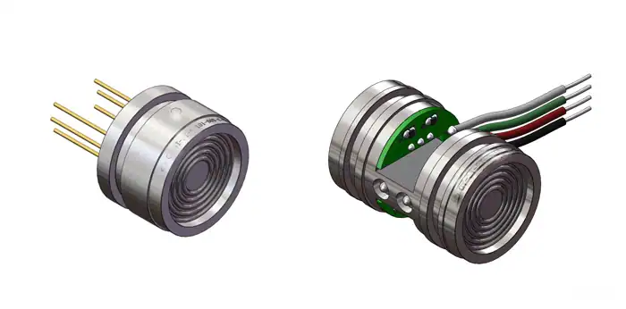
Read the overload as a multiple of full scale, and remember it is not constant. On our ceramic HM12-UC elements, the overload runs from about 10× full scale at the high ranges to 200× at the lowest ranges, because a low-range diaphragm is stiffer relative to its span. That is the opposite of intuition, so size from your spike, not your nominal. A diffused-silicon element such as the HE10 trades that headroom for range. It covers 0–20 kPa up to 0–600 bar (8,702 psi), with overload at 1.5–2× and burst near 4× full scale for ranges up to 100 MPa. If your application sees water hammer or pump pulsation, pick the range so the worst spike still lands inside the overload rating, rather than the range that merely brackets normal operation.
Sensing element: ceramic capacitive versus diffused silicon
The sensing technology sets the envelope for media compatibility, overload and temperature, so compare the numbers directly. The two we reach for most on OEM work are dry ceramic capacitive and diffused silicon, and the trade-off is real.
| Attribute | Ceramic capacitive (HM12-UC) | Diffused silicon (HE10) |
|---|---|---|
| Typical accuracy | ±0.075% FS (best) | ±0.5% FS typical |
| Overload | 10× to 200× FS | 1.5–2× FS, burst ~4× FS |
| Max range | to 7 MPa | to 600 bar (60 MPa) |
| Response time | standard | ≤ 4 ms (fast) |
| Operating temperature | −40 to 125 °C | −20 to +85 °C |
| Media | dry media compatible with alumina; isolation diaphragm option | needs 316L isolation, broad chemical compatibility |
| Output | analog mV (ratiometric) or digital | 4–20 mA, 0–5 V, 1–5 V, 0.5–4.5 V, I²C |
The pattern is clear once you see the numbers. Ceramic is the better pick when you need very high accuracy, very high overload tolerance, or a wide temperature window, and your range stays at or below a few MPa. Its 99.99% high-purity alumina diaphragm also shrugs off media that would corrode a metal one. Silicon is best suited when you need a high range, a fast response, or a wide menu of outputs on one part, and ±0.5% FS satisfies your loop. Neither is better in the abstract. They win in different corners of the spec sheet.
Accuracy, repeatability and temperature you can trust
Datasheets quote accuracy in ways that are easy to misread, so check what the percentage references. A figure in %FS is a fixed band across the whole span, so it looks worse near the bottom of the range. A figure in %reading scales with the measured value. Our HM12-UC family states ±0.075% FS at its best grade, with long-term stability of ±0.05% FS per year, so you can budget drift over a service interval instead of guessing.
Pay equal attention to the compensated temperature range, because accuracy only holds inside it. The HM12-UC is compensated over −20 to 80 °C, even though it operates to −40 to 125 °C, and it holds a typical zero and sensitivity drift of ±0.005% FS per °C. If your equipment runs hot, confirm your worst-case ambient sits inside the compensated band, not just the operating band. If it does not, order a wider compensation.
Customization, MOQ, and lead-time reality
This is the part product pages rarely spell out, and it is where most OEM projects stall. The configurable items are the pressure range, the output, the process connection thread, the electrical connector, and the factory calibration points. On the HE10, the process connection can be M20×1.5, G1/4 (per ISO 228:2000), 1/4 NPT, or a custom thread. The electrical side can be a flying lead, a Hirschmann DIN-A, or an M12 connector, rated IP65 at the connector and IP67 on the cable version under IEC 60529:2013. Lock those five fields and you have a part number you can reorder.
Be realistic about volume and timing. Standard configurations carry a low minimum order quantity and ship quickly. A custom range, a non-standard connector, or a tightened calibration grade raises the minimum and extends the lead time, because it means a dedicated build and test setup. The practical move is to request samples in your exact configuration first, qualify them in your equipment, then place the production order against the same part number. We would rather quote a custom port up front than have you design around a standard part that does not quite fit.
Three OEM scenarios, three spec calls
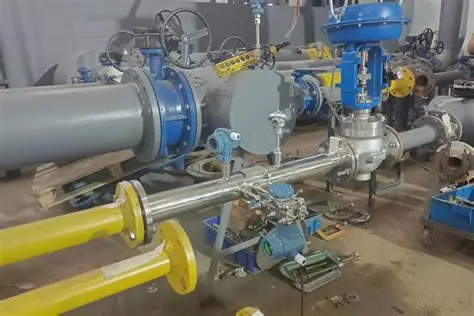
The decisions above land differently depending on what you build, so here is how they resolve in three common cases. On a hydraulic power unit, prioritise overload: a ceramic element with high full-scale-multiple headroom survives the transients that kill an under-specified silicon part. On an HVAC-R compressor, prioritise temperature and cost: a compact ratiometric sensor compensated across the compressor’s ambient range usually strikes the right balance. On a mobile or battery-powered device, prioritise supply and integration: a digital or low-power output that reads straight into the microcontroller saves both an ADC channel and current budget.
A copy-paste OEM spec checklist
Before you send a request for quote, fix every line below. A complete spec gets you an accurate price and a part that drops into your design without a second iteration.
- Pressure range (and reference: gauge, absolute or compound)
- Worst-case overpressure / spike, so overload can be sized to it
- Output (ratiometric, amplified, 4–20 mA, mV/V, or digital)
- Supply voltage available on your board
- Accuracy grade and the compensated temperature range you need
- Operating temperature at the sensor, worst case
- Media and required wetted material
- Process connection thread and pressure port
- Electrical connection (cable, Hirschmann, M12, or board pins)
- Ingress protection required
- Certifications your end product must carry
- Annual volume and required first-article / sample timing
Get those twelve lines on paper and the sourcing conversation becomes a quote, not a discovery exercise. For a starting point, our OEM pressure sensors and transducers range lists the ceramic HM12-UC and silicon HE-series options, and the HE10 page carries the full configuration table.
Specifying an OEM pressure transducer?
Send us your range, worst-case spike, output, supply voltage, and target volume, and we will configure a ceramic or silicon transducer with the right port, connector, and calibration for your build.
OEM pressure transducers from HMK TECH
HMK builds OEM pressure sensors on both elements this guide weighs. The diffused-silicon HM20 platform covers general OEM duty — gauge or absolute, vacuum to 100 MPa, up to 2× overload, ±0.25% FS, a 4–20 mA or ratiometric voltage output, IP65/IP67 housings and an Ex ia option — while the ceramic-capacitive HM12-UC family handles media that attack silicon. Both are built to be re-ranged and re-housed for your product, so fix the output and pressure port first, then ask for MOQ and lead time against your annual volume.
Frequently Asked Questions
What is the difference between a ratiometric and an amplified pressure transducer output?
A ratiometric output is referenced to the supply voltage, so its zero and span scale with the rail. A 0.5–4.5 V ratiometric sensor on a 5 V supply puts the sensor and the ADC on the same reference, so supply variation cancels. An amplified output such as 0–5 V or 1–5 V delivers a fixed voltage independent of small supply changes, which is more forgiving when the sensor supply and the ADC reference are not the same node.
Can I get an OEM pressure transducer with a custom pressure range or port thread?
Yes. The range, output, process connection and electrical connector are all configurable, and custom threads such as a specific metric or NPT port are routine. A custom range or connector typically raises the minimum order quantity and lead time versus a standard configuration, so request samples in your exact build before the production order.
What is the typical MOQ and lead time for OEM pressure sensors?
Standard configurations carry a low minimum and ship quickly. Custom ranges, non-standard connectors or tightened calibration grades require a dedicated build and test setup, which raises the minimum and extends lead time. The fastest route is a sample build in your configuration first, then a production order against the qualified part number.
Is a ceramic or silicon sensing element better for my media?
Choose ceramic capacitive for very high accuracy, high overload tolerance, a wide temperature window, and ranges at or below a few MPa; its alumina diaphragm also resists media that corrode metal. Choose diffused silicon for high ranges, fast response, and a broad output menu, where ±0.5% FS is acceptable. Confirm the wetted material against your fluid before you commit.
What does “compensated temperature range” mean on an OEM datasheet?
It is the temperature band over which the stated accuracy is guaranteed, and it is usually narrower than the operating range. A sensor compensated over −20 to 80 °C may operate to −40 to 125 °C, but outside the compensated band the error grows. Match your worst-case ambient to the compensated band, or order a wider compensation.