NAMUR NE 43 Fault Signaling: What 3.6 mA and 21 mA Mean
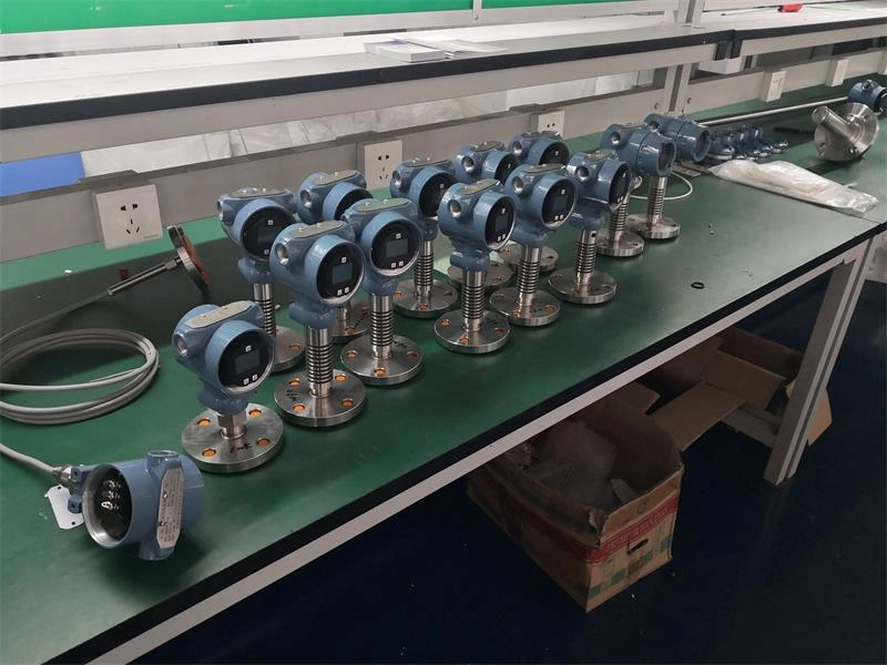
A 4-20 mA loop carries a measurement between 4 mA and 20 mA. That leaves an obvious hole. If the transmitter itself fails, what current should it send? And how does the control system tell that apart from a real reading near the end of the range? NAMUR NE 43 answers that question with a set of bands rather than a single number. This article assumes you already know how two wires carry both power and signal, and picks up where the measuring range ends: the bands themselves, what three manufacturers actually implement, and the two places the signal gets thrown away before anyone sees it.
Alarm and Saturation Bands on a 4-20 mA Loop
A NAMUR-compliant transmitter can put its output in one of several zones. Each zone carries a different instruction for the operator.
| Current | Zone | What it means |
|---|---|---|
| ≤ 3.6 mA | Low fault | The device has diagnosed itself as failed |
| 3.6 to 3.8 mA | Undefined | A compliant device should not sit here |
| 3.8 to 4 mA | Low saturation | Process below calibrated range, device healthy |
| 4 to 20 mA | Measuring range | Normal reading, 0 to 100 percent of span |
| 20 to 20.5 mA | High saturation | Process above calibrated range, device healthy |
| 20.5 to 21 mA | Undefined | A compliant device should not sit here |
| ≥ 21 mA | High fault | The device has diagnosed itself as failed |
The split that matters lies between saturation and fault. Saturation says the measurement is real but the process has moved outside the range you calibrated. A fault says the reading carries no information at all. One calls for a process decision. The other calls for a technician, and the symptom-first troubleshooting sequence starts from there.
A note on where these figures come from. This article works from the published configuration and product datasheets of Emerson, Endress+Hauser and Yokogawa, listed at the end. It does not work from the NE 43 text itself, which NAMUR distributes through its own office. Where the three manufacturers implement different values, the article says so.
The 2021 Revision of NE 43
Most of the NE 43 material in circulation describes the 2003 edition. NAMUR revised the recommendation on 26 July 2021. Its own announcement says the changes “mainly concern the introduction of a safety margin for signal detection in control systems and the device behavior during initialization.”
Two things follow from that sentence. First, NAMUR moved part of its attention to the receiving end. A fault current only does its job if the input card and the application logic preserve it, which a later section here takes up. Second, initialization. A transmitter that is powering up has not finished its self-checks, and its output during those first moments can land in a fault band. If you commission a unit and see a brief high-fault alarm at power-up, the recommendation now addresses that behavior rather than leaving it as an oddity of one brand.
The full title narrows the scope usefully: “Standardization of the Signal Level for the Failure Information of Digital Transmitters.” NE 43 covers microprocessor-based devices that can diagnose themselves. A purely analog sensor has nothing to report.
Why Vendor Datasheets Print Different Numbers
Search for NE 43 alarm levels and you will find 3.6, 3.75, 21, 21.6, 21.75 and 22.5 mA, all presented as correct. They are all correct. NE 43 fixes boundaries rather than points. Any value at or below 3.6 mA works as a low fault, any value at or above 21 mA works as a high fault, and manufacturers pick their own numbers inside that freedom.
| Source | Low alarm | Low saturation | High saturation | High alarm |
|---|---|---|---|---|
| Boundary all three converge on | ≤ 3.6 | 3.8 | 20.5 | ≥ 21.0 |
| Rosemount 3051, standard levels | 3.75 | 3.90 | 20.80 | 21.75 |
| Rosemount 3051, NAMUR codes C4 / CN | 3.60 | 3.80 | 20.50 | 22.50 |
| Rosemount 644, standard levels | 3.75 | 3.90 | 20.5 | 21.75 |
| Endress+Hauser Cerabar S / Deltabar S | 3.6 fixed | 3.8 default | 20.5 | 21 to 23, set to 22 |
| Yokogawa EJA-E with option C2 / C3 | 3.2 or less | 3.8 | 20.5 | 21.6 or more |
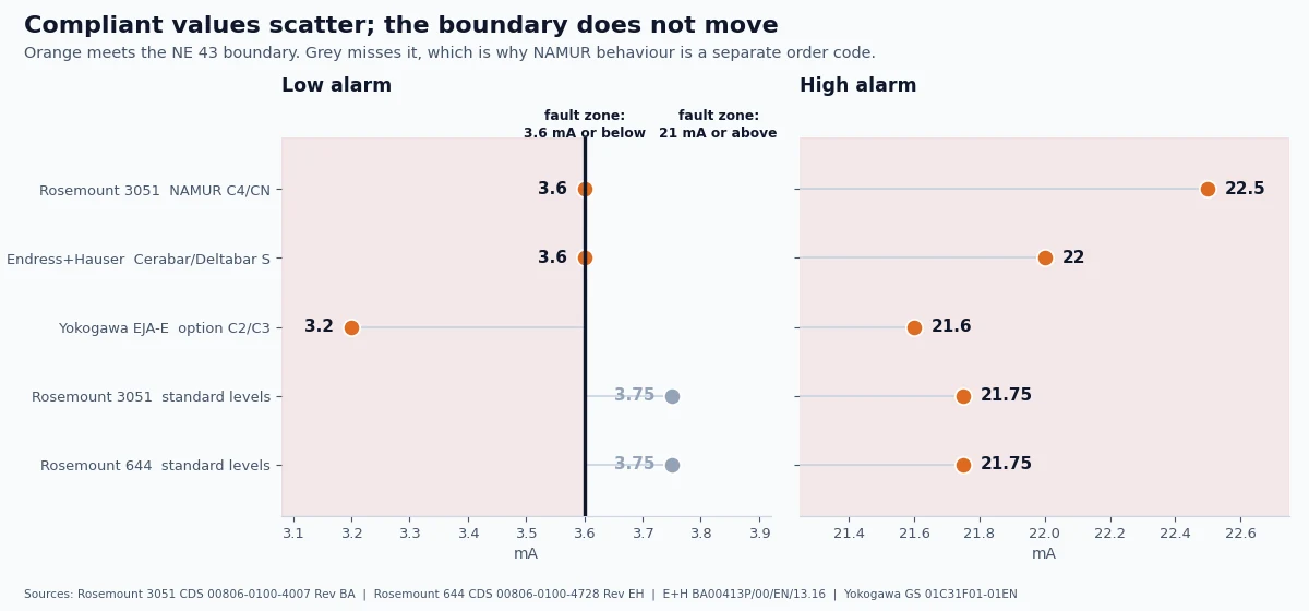
Read the low-alarm column. Emerson uses 3.60 mA, Endress+Hauser fixes 3.6 mA, Yokogawa drives to 3.2 mA or below. All three satisfy a boundary of 3.6 mA or less. The high-alarm column spreads wider still, from 21.6 mA to 22.5 mA.
Three details in that table deserve a closer look. Emerson’s own product lines disagree with each other, since the 3051 configuration sheet gives a standard high saturation of 20.80 mA while the 644 sheet gives 20.5 mA. Emerson also documents the constraint that explains why the undefined gaps exist. Its configuration sheet states that the high alarm “must be 0.1 mA greater than high saturation value.” Yokogawa’s NAMUR option narrows the output rather than widening it: the standard EJA-E range runs 3.6 to 21.6 mA, while codes C2 and C3 limit the signal to 3.8 to 20.5 mA.
One figure in that table does not meet the boundary at all. Rosemount’s standard low alarm of 3.75 mA sits above 3.6 mA, so a transmitter shipped on standard levels never reaches the low fault band that NE 43 asks for. Its standard high alarm of 21.75 mA clears the high boundary without trouble. The low end is where standard levels fall short, and that single number is the reason NAMUR behavior carries its own order code.
Notice what does not vary. All three set saturation at 3.8 mA and 20.5 mA. The saturation band is the rigid part of NE 43, and the alarm values are where manufacturers exercise judgment.
NAMUR Compliance as an Order Code
NE 43 behavior is not a default that every transmitter arrives with. On the Rosemount 2051 it is option code C4 for high alarm or CN for low alarm. The product datasheet then settles the matter with a footnote: “NAMUR-Compliant operation is pre-set at the factory and cannot be changed to standard operation in the field.” Yokogawa handles it the same way through order codes C2 and C3.
So if your specification says the loop shall comply with NE 43, that requirement has to reach the order. A transmitter delivered with standard alarm levels will fault at 21.75 mA instead of 22.5 mA. That current still sits outside the measuring range and still reads as a fault, but your DCS logic expects a different number. Check the model string on the nameplate during acceptance rather than assuming. The same logic applies to HMK transmitters, since models like the HM21R submersible ship with a choice of 4-20 mA, 1-5 V or 0-5 V outputs, and only the current-loop option carries this fault scheme.
Alarm Currents vs. Input-Card Limits
Here is where a correctly configured transmitter still fails to raise an alarm.
Analog input modules for 4-20 mA service carry their own diagnostic and over-range ceilings, commonly in the 21 to 22 mA region. Above that ceiling a module reports an overflow, clamps at its maximum count, or flags the channel as faulty. Now connect a Rosemount ordered with NAMUR high alarm at 22.50 mA, or an Endress+Hauser transmitter shipped with its 22 mA factory setting. The transmitter announces a high fault. The module may report an overflow or a generic channel fault instead. Those are different faults, they send maintenance in different directions, and the operator sees the wrong one.
The low end has its own version. Endress+Hauser’s Cerabar S manual carries a warning beside the parameter that sets the lower current limit: “some switching units do not accept current values lower than 4.0 mA.” A 3.8 mA low saturation only helps if everything downstream can read it.
Check the loop can still drive the current, too. Yokogawa sizes the permissible load for its EJA-E series from R = (E − 10.5) / 0.0244, and 0.0244 is 24.4 mA, not 20 mA. They sized it for the fault current. A loop scraping by at 20 mA can run short of terminal voltage exactly when the transmitter announces a fault, and the loop resistance calculator gives the margin.
A software failure mode sits alongside both, and it is the common one. A module can detect the condition correctly and set a status or quality bit. The application logic then compares only the scaled engineering value against process alarm limits, and never reads that bit. The PLC receives the NE 43 information and discards it internally. This is the receiving-end problem that the 2021 revision takes up with its safety margin for signal detection.
Choosing Upscale or Downscale Failure Direction
A common rule of thumb says two-wire transmitters should use upscale. That rule answers the wrong question. The direction should follow from what happens to the process when the signal lies.
On a Rosemount 644 temperature transmitter the choice is a physical switch labeled “Failure mode switch: High / Low,” and it leaves the factory set to High. That default makes sense once you work through a heater. A thermocouple on a furnace outlet opens, the transmitter drives downscale, and the controller reads a very low temperature. It then calls for more heat. The failure feeds the runaway, so upscale is the only safe direction there.
Change the process and the answer changes with it.
| Loop | Upscale on failure | Downscale on failure | Preferred |
|---|---|---|---|
| Furnace outlet temperature, TC input | Reads high, controller cuts heat | Reads low, controller adds heat and drives a runaway | Upscale |
| Tank fill against a high-level trip | Reads full, spurious shutdown of a healthy fill | Reads empty, fill continues toward overflow | Downscale plus an independent interlock |
| Compressor low-low suction pressure trip | Reads high, real low-suction event can pass unnoticed | Reads low, spurious machine trip | Upscale plus an independent interlock |
| Furnace fuel-gas pressure, safety shutdown | Reads high, valve closes, safe state | Reads low, controller may open the valve further | Upscale |
So the direction follows from the process, not from the wiring. Work through what the controller does with a false low reading, then with a false high reading, on that specific loop. Pick whichever failure leaves the plant in the safer state. If both readings lead somewhere unsafe, failure direction is not the right tool, and the function needs an independent interlock.
Sensor Burnout vs. NE 43 Fault Current
These two get treated as one thing, and they are not.
Thermocouple burnout detection sits on the input side. The instrument injects a very small bias current, in the nanoamp to microamp region, through a high-value resistor across the thermocouple circuit. While the thermocouple stays intact, that current has no meaningful effect on the reading. When the thermocouple opens, the current drives the input hard to one rail, and the instrument knows the sensor is gone. This is a detection mechanism. Choosing a grounded or ungrounded junction changes how that input circuit behaves, and an RTD input handles the same job through its two-, three- or four-wire connection.
NE 43 sits on the output side. Once the transmitter has decided a fault exists, whether from a burnout circuit or any other diagnostic, it drives its 4-20 mA output into the fault band. This is a reporting mechanism.
The chain runs in order. The thermocouple opens. The input circuit detects it. The transmitter declares a sensor fault. The output then moves to 3.6 mA or 21 mA according to the failure direction you set.
One historical point explains why NE 43 exists at all. Older burnout schemes drove the output to 4 mA or 20 mA. Both of those are legal readings. A control system receiving 20 mA cannot separate a genuine full-scale process from a dead sensor, and removing that ambiguity is the whole purpose of the recommendation.
Verifying Fault Signaling During Loop Checks
Simulating the transmitter is the only way to know the whole chain works. The test has one trap in it.
Put a loop calibrator in place of the transmitter and walk the current through the steps below, holding each one long enough for the control system to confirm what it sees.
| Step | Current | What the DCS should show |
|---|---|---|
| 1 | 4.0 mA | 0 percent, no alarm |
| 2 | 3.9 mA | Slightly negative or 0 percent, no device fault |
| 3 | 3.8 mA | Low saturation, process alarm only |
| 4 | 3.6 mA | Low device fault, maintenance alarm |
| 5 | 3.5 mA | Low device fault; confirm the card still returns a value here |
| 6 | 20.0 mA | 100 percent, no alarm |
| 7 | 20.5 mA | High saturation, process alarm only |
| 8 | 21.6 mA | High device fault, maintenance alarm |
| 9 | 22.5 mA | High device fault, card must not overflow |
You are checking three things at once. The input card still reports a usable value at each point. Saturation and fault raise different annunciations. And the high end does not overflow before reaching your transmitter’s alarm current. For the engineering value the DCS should show at each step, the 4-20 mA signal calculator converts both ways.
The trap is dwell time. A widely cited practice holds the fault signal for at least four seconds and at least two scan cycles before the control system confirms it, which stops noise from raising alarms. Sweep the calibrator quickly and nothing annunciates. The loop then looks broken while it is behaving correctly. Hold each step.
Measure at both ends of the loop while you do it, and a case published by Yunrun Instrument shows why. On a loop where the transmitter’s own indicator and a handheld communicator both read 16 mA, the DCS showed the point as bad. The card checked out. Measuring at the transmitter terminals returned 16 mA, and measuring at the DCS card input returned 3 mA. That left 13 mA going somewhere else. A megohmmeter found insulation leakage on the signal negative conductor, which was bleeding current away before it reached the card, and repairing the insulation brought the DCS reading back into agreement with the transmitter.
Look at what the control system did with that 3 mA. The current sat below 3.6 mA, so the DCS read it as a device fault and flagged the point. That was the correct response to the current arriving at its terminals and the wrong conclusion about which device had failed. A fault band tells you the signal is untrustworthy. It does not tell you where the trouble sits, and on a two-wire loop the wiring is as likely a culprit as the transmitter.
Frequently Asked Questions
What is the meaning of NAMUR NE 43?
NE 43 is a NAMUR recommendation titled “Standardization of the Signal Level for the Failure Information of Digital Transmitters.” It defines how a self-diagnosing transmitter should use current levels outside 4-20 mA to report its own failure. A control system can then separate a device fault from a real process excursion. NAMUR dates the current edition 26 July 2021.
What is the limit of NAMUR NE 43?
Two boundaries matter. A compliant device signals a fault at 3.6 mA or below, or at 21 mA or above. Control systems treat 3.8 to 20.5 mA as valid measurement including saturation. The narrow gaps at 3.6 to 3.8 mA and 20.5 to 21 mA stay undefined so the two states never overlap. Manufacturers choose their own alarm values outside the boundaries, which explains datasheets showing anything from 3.2 to 3.75 mA at the low end and 21.6 to 22.5 mA at the high end.
What is the NAMUR standard?
NAMUR is a German-based international user association for automation technology in the process industries. Its documents are recommendations rather than legally binding standards, and NE 43 is one of a numbered series. Compliance works contractually, so it takes effect when you write it into a specification and order a transmitter configured for it.
How does NE 43 relate to NE 131?
They are separate recommendations in the same NAMUR series and cover different subjects. NAMUR published NE 131 as its own document. If a specification cites both, treat them as independent requirements and obtain each text from the NAMUR office rather than assuming one supersedes the other.
Does NE 43 apply to a 1-5 V output?
No. Yokogawa’s EJA-E specification states that the 1 to 5 V output “is applied to output signal code Q which is noncompliant to NAMUR NE43.” NE 43 builds on current-loop behavior. Choosing a voltage output means giving up this fault-reporting scheme and finding another way to detect a dead transmitter, which is one more reason to weigh the output signal type before the range.
Sources
Analog signal ranges follow ANSI/ISA-50.00.01-1975 (R2012), which established 4-20 mA as the process signal. Safety-related transmitter certification referenced here is to IEC 61508:2010.
| Publisher | Document | Reference |
|---|---|---|
| NAMUR | NE 43 has been revised | Edition 2021-07-26 |
| Emerson | Rosemount 3051 Configuration Data Sheet | 00806-0100-4007 Rev BA |
| Emerson | Rosemount 644 Configuration Data Sheet | 00806-0100-4728 Rev EH |
| Emerson | Rosemount 2051 Product Data Sheet | 00813-0100-4101 Rev MA |
| Endress+Hauser | Cerabar S / Deltabar S Operating Instructions | BA00413P/00/EN/13.16 |
| Yokogawa | EJA510E and EJA530E General Specifications | GS 01C31F01-01EN |
| Yunrun Instrument | Fault checking on 4-20 mA transmitter loops under different supply modes | Field case, signal-line leakage |
Specifying fault behavior on your next order?
Send us the loop details and the alarm direction the process needs, and we will confirm what the transmitter can be configured to do before you order.