Pressure Transmitter Symbol on P&ID: PT, PIT, PDT Guide
A P&ID drops three letters inside a circle and assumes you already know what they mean. PT, PIT, and PDT each describe a different pressure transmitter with a different function, different field wiring, often a different price tier, yet many drawings give you no legend page to lean on. This guide walks through the three transmitter symbols you actually meet on a working P&ID, what changed in ANSI/ISA-5.1-2024, and how the Chinese HG/T 20505-2014 system maps onto the same shapes.
Quick Reference: What PT, PIT, and PDT Look Like at a Glance
Three letters, three jobs. PT is a pressure transmitter that sends a signal and shows nothing locally. PIT does the same but adds a dial or digital display you can read on the equipment. PDT measures the difference between two pressure ports and transmits that delta. The bubble itself is identical for all three: a circle, sometimes with a horizontal line through it, and the function letters are what carry the meaning. In our own field walk-downs, the same loop number can repeat on three pages and the only way to tell which page owns the dial is the second letter.
The Instrument Bubble: Shape, Location, and the Four-Line Rule
The bubble carries two pieces of information: the letters tell you what the device measures and does; the horizontal line through (or around) the bubble tells you where it lives. ANSI/ISA-5.1-2024 keeps the original four cases:
- No line: field-mounted, sitting on the pipe or vessel itself.
- Single solid line: primary control room, accessible to the operator.
- Dashed line: auxiliary location, accessible to the operator.
- Double solid line: primary control room, behind the panel, normally inaccessible.
Square bubbles signal shared-display or shared-control devices, typically a tag in the DCS rather than a discrete instrument. Hexagonal bubbles are reserved for computing or logic functions. The discrete-switch cousin of these symbols is covered in our pressure switch symbol guide. Chinese drawings under HG/T 20505-2014 use a shape vocabulary broadly aligned with ISA — bubble forms, line conventions, and modifier letters all map onto the ISA originals, so a drawing translated between an ISA package and a Sinopec or Wanhua spec is readable side-by-side without a redraw, though the legend page should always confirm edition.
Decoding the Tag Number: PT-101 Anatomy
A tag like PT-101 looks atomic but breaks into four parts. The first letter is the measured variable: P for pressure, T for temperature, F for flow. Optional modifier letters follow before the function letter: D for differential, I for indicating, R for recording. The function letter is what the device does: T for transmitter, I for indicator, C for controller. The number is the loop ID, often three digits keyed to a unit area, sometimes with a redundant suffix A or B. If the loop reads a vacuum value, our can gauge pressure be negative explainer covers what that negative number actually means at the bubble.
A real refinery example: PT-1101A and PT-1101B sit at the same nozzle, wired into a 1oo2 voted shutdown loop. The A/B suffix tells the operator they are redundant, not duplicates with separate jobs. A second tag, PDIT-205, adds two modifiers: pressure-differential-indicating-transmitter, the one that has both a local readout and a 4-20 mA output. The decoding pattern is described in detail in the Control.com instrumentation tags chapter, which remains the most widely cited online reference for the convention.
| Position | Letter(s) | Meaning | Example |
|---|---|---|---|
| 1 | P | Pressure (the measured variable) | PT, PI, PIC |
| 2 (mod) | D, I, R | Differential / Indicating / Recording | PDT, PIT, PRT |
| 3+ | T, I, C, R | Transmitter / Indicator / Controller / Recorder | PT, PI, PIC |
| Loop | 101 | Loop ID (unit area + sequence) | PT-101 |
| Suffix | A/B | Redundant pair | PT-1101A |
PT vs PIT vs PDT: When Each One Is the Right Pick
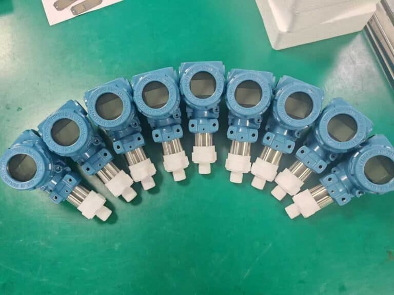
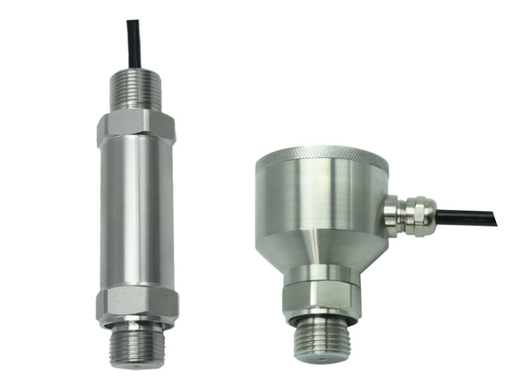
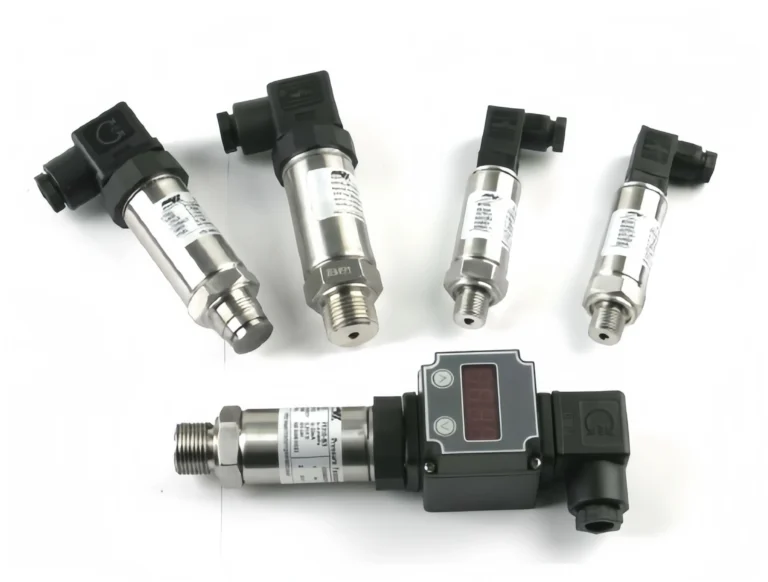
The three families look the same on paper and behave differently in the field. PT is the simplest: a sensor and a 4-20 mA output, no display, lowest cost, ideal where the operator never stands next to the pipe. PIT adds a local indicator (usually an LCD on the housing) at a small premium over the bare-PT version; pick it when a maintenance walk-down needs to confirm process value without a handheld. PDT measures the difference between two ports and is the workhorse behind orifice flow, filter monitoring, and level in pressurized tanks. For a fuller picture of the transmitter families themselves, see our pressure transmitter types pillar.
| Family | Indicates locally? | Typical output | Typical range | Where it wins | HMK SKU example |
|---|---|---|---|---|---|
| PT | No | 4-20 mA, HART, Fieldbus | 0-1 bar to 0-60 MPa | Pipe runs, vessels, deep skids | HM22 High-Accuracy, HM24 Low-Cost |
| PIT | Yes (LCD on housing) | 4-20 mA + display | Same as PT | Walk-down checks, packaged skids | HM29 Digital Intelligent |
| PDT | No (or with optional display) | 4-20 mA + HART common | low Pa to tens of MPa span | Orifice flow, filter DP, level in closed tanks | HM3051 Smart DP, HM1151 Capacitive DP |
Two notes from the field. First, never assume PIT means “no DCS link”; the display sits on top of the same 4-20 mA loop, not instead of it. Second, on filter monitoring loops we have seen designers spec a PDT when a single PT pair plus DCS subtraction would have cost less and given more diagnostics. The PDT wins on response time but loses on flexibility. Choose with care.
Signal Line Types: Pneumatic, Electrical, Digital, and the Rest
The line connecting the bubble to the process or to the next loop tells you what travels along it. ISA-5.1-2024 keeps the same six families that have been in the standard for two decades:
| Line style | Signal | Where it shows up |
|---|---|---|
| Solid line | Process pipe or tube (mechanical connection) | Sensing line, impulse tubing |
| Dashed line | Electrical signal | 4-20 mA loops, on/off contacts |
| Long-dash-cross-dash | Pneumatic signal | Older or hazardous-area control loops |
| Solid line with circles | Digital signal / fieldbus | HART overlay, FOUNDATION Fieldbus, PROFIBUS PA |
| Double slash | Capillary (filled system) | Diaphragm seals, remote-seal DP transmitters |
| Long-dash-double-cross | Hydraulic signal | Hydraulic actuator loops |
The distinction matters during commissioning. A PT bubble connected to its loop by a dashed line is sending 4-20 mA, so the loop check is a milliamp meter; the same PT drawn with a circle-dot line means the loop already runs HART or FF, and the field tech needs a handheld instead. For the analog dial end of the same loop, where scale, accuracy class, and division steps matter more than signal type, see our pressure gauge reading guide.
What ANSI/ISA-5.1-2024 Changed and Why Your Old Legend May Be Wrong
The 2024 revision is the first major rework since 2009. Three changes most often catch out spec engineers using the older edition:
First, digital protocols got their own first-class symbology. The 2009 edition allowed HART/Fieldbus marks but did not codify them; 2024 standardizes the circle-dot line and adds suffix letters for protocol family (commonly seen as H for HART, F for FOUNDATION, and P for PROFIBUS PA — your plant's symbol legend is the final word on local convention). The ISA-5.1 committee page tracks current edition status and errata.
Second, the shared-display and shared-control bubble was redefined. A DCS-only tag now uses a square bubble with a single solid line through it, and the older hexagonal shape (which used to do double duty) is reserved for pure logic functions only.
Third, safety-related tags now carry an explicit SIL marker per IEC 61511. The 2009 edition treated SIL marking as user-defined; the 2024 edition standardizes it as a parenthesized suffix.
| Topic | ISA-5.1-2009 | ISA-5.1-2024 | HG/T 20505-2014 (China) |
|---|---|---|---|
| Digital protocol line | Implementation note | Standardized circle-dot + suffix | Aligned via implementation note |
| Shared display bubble | Hexagon or square (ambiguous) | Square + solid line | Square + solid line |
| Safety SIL marker | User-defined | Standardized parenthesized suffix | Per GB equivalent (in revision) |
If your plant standard freezes on 2009, you are not wrong (many sites do), but a contractor delivering a 2024 package will surprise you on three pages without flagging it. Ask up front. Accuracy class on the gauge side of the same loop follows a parallel ladder — see our pressure gauge accuracy class guide for the 0.1 to 4.0 progression.
HART, Foundation Fieldbus, and PROFIBUS: How New Symbols Mark Digital Protocols
A PT bubble with a circle-dot line and a small “.H” next to the loop number is a HART transmitter. “.F” indicates FOUNDATION Fieldbus and “.P” indicates PROFIBUS PA, both per ISA-5.1-2024 conventions. On a real spec sheet for our HM3051 Smart Differential Pressure Transmitter, the HART variant carries a .H protocol mark wherever the loop appears, and the PROFIBUS variant carries a .P mark — under whichever exact convention your plant has frozen for the package. The mark is small but it removes a whole conversation between the controls engineer and the field-instrumentation team: the protocol is decided at the drawing, not at the cabinet.
Frequently Asked Questions
Is PT on a P&ID always a pressure transmitter?
Yes. Under ANSI/ISA-5.1-2024 the first letter P locks the variable to pressure, and the function letter T locks the role to transmitter. If you see PTH or PTS the suffix is a user-defined option, but the base PT meaning is fixed.
What does a solid horizontal line through the bubble mean?
The instrument is located in the primary control room and is accessible to the operator. No line means field-mounted on the pipe or vessel. A dashed line means auxiliary location. A double solid line means primary control room but behind a panel, not accessible.
PT versus PI: what is the difference if both show pressure?
PI is a pressure indicator only: a dial or digital readout, no transmission, no 4-20 mA output. PT is a transmitter: signal to the DCS, no local display unless you add the I modifier to make it PIT.
Can I use ISA-5.1-2024 symbols on a drawing that follows the 2009 edition?
Not without a revision-control note. The two editions are mostly compatible, but the digital-protocol lines and the shared-display bubble changed enough that mixing them silently will confuse the next reviewer. Flag the edition in the title block.
Does HMK provide a P&ID symbol library for download?
Our engineering team can supply an ISA-5.1-2024-compatible symbol pack for AutoCAD and SmartPlant on request. Contact us with the protocol family you need (HART, FF, PROFIBUS PA).
Once you can read a PT, PIT, or PDT cold off a drawing, the rest of the loop falls into place: signal type from the line style, location from the bubble line, function from the letter cluster. For pressure transmitters that ship with ISA-5.1-2024 symbol packs and HART, FF, or PROFIBUS PA marking ready for your drawing set, look at our pressure transmitter range or contact our engineering team for a symbol pack that drops into your CAD.