Electronic Pressure Switch: How to Choose and Set One
You have already decided to use a pressure switch rather than a continuous transmitter. The open question is narrower: should you specify an electronic (digital) switch or a mechanical one, and once it is on the skid, how do you set the trip point so the relay does not chatter? Both come down to a few decisions you can make at the bench: how the switch decides to flip a contact, where a mechanical unit still beats an electronic one, and what setpoint and deadband to write on the bill of materials.
If you only need the P&ID symbol, or you are still weighing a switch against a transmitter, those are different questions. See our guide on reading the pressure switch symbol and on a pressure switch versus a pressure transmitter.
How does an electronic pressure switch work?
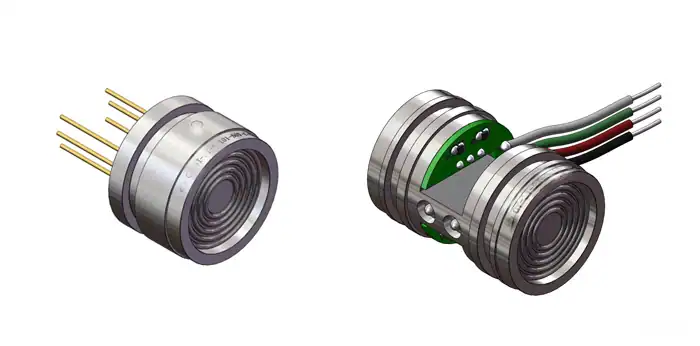
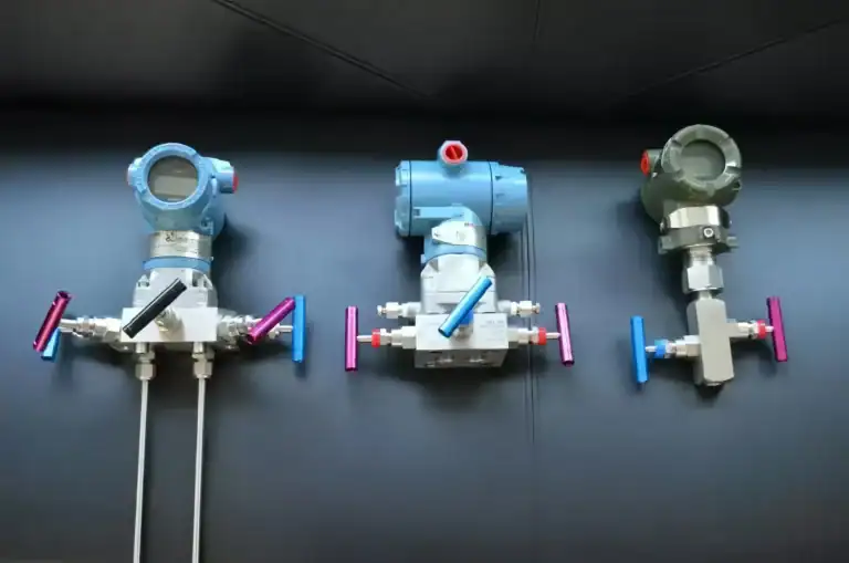
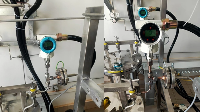
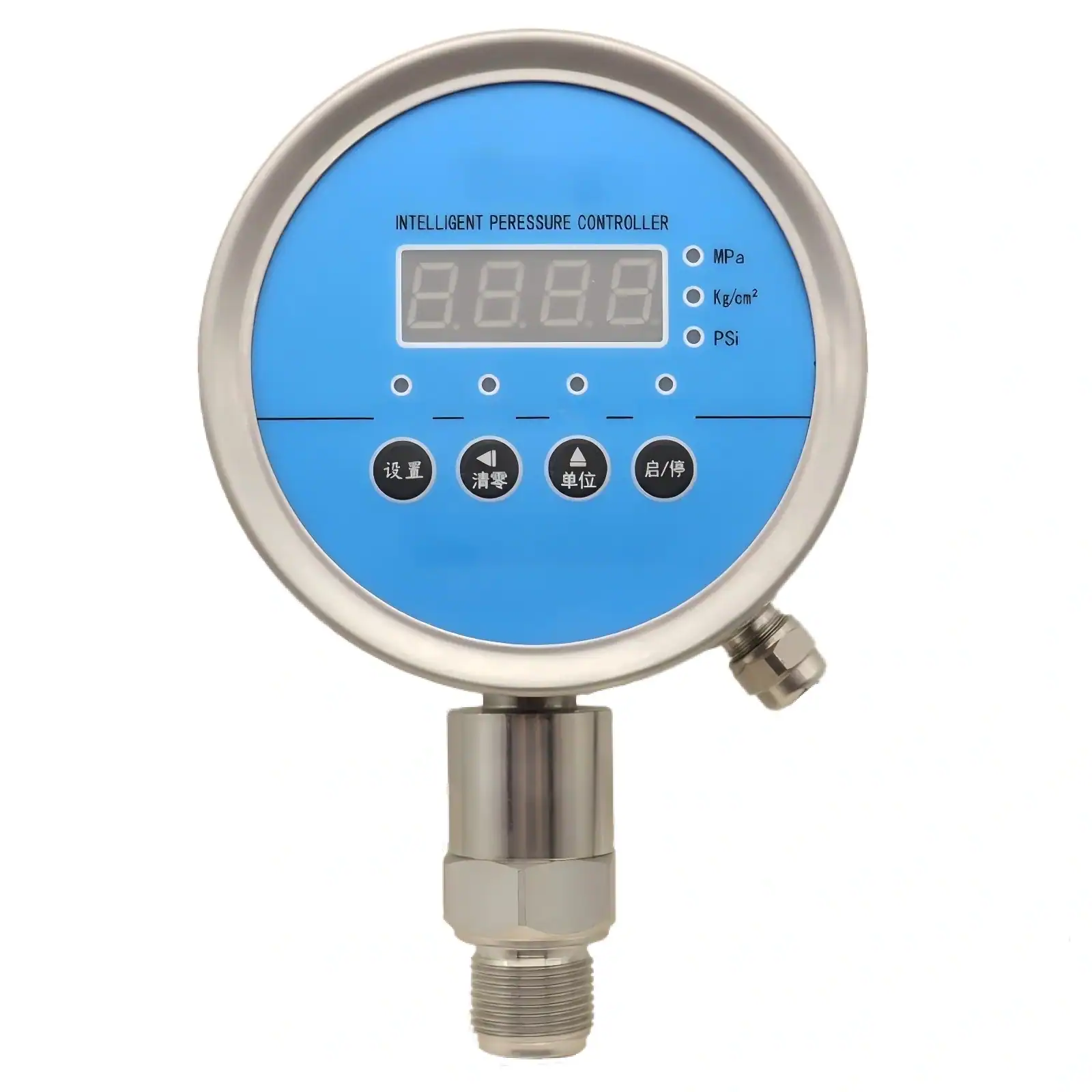
An electronic pressure switch is a small pressure sensor with a comparator and a relay bolted to its output. The sensing element, usually a piezoresistive or ceramic cell, turns process pressure into a voltage. A microcontroller reads that voltage many times a second, compares it against the trip point you stored, and drives a relay or a transistor output when the reading crosses the line. A local display shows the live pressure, so you set the trip point on the unit itself instead of chasing it with a hand pump and a reference gauge.
That architecture is the same one inside a pressure transmitter; the switch simply adds the decision logic and the contact. Many digital switches also bring out a parallel 4-20 mA signal, so one device gives you both a hard trip for the pump and a continuous reading for the PLC.
Electronic vs mechanical: the real differences
A mechanical switch needs no power. Process pressure pushes on a piston, a diaphragm, or a Bourdon tube, and at a set force a snap-action microswitch flips. That simplicity is its strength and its limit. The electronic version needs a DC supply, but in return it gives you a settable trip point anywhere in the range, a readable display, and a tighter, programmable reset.
| Attribute | Mechanical switch | Electronic switch |
|---|---|---|
| Power | None required | DC supply (often 24 V) |
| Setpoint adjustment | Limited band, screw-set | Anywhere in range, on-screen |
| Reset point (deadband) | Wide, mostly fixed | Narrow and programmable |
| Local reading | None | LED or LCD display |
| Accuracy | Coarse, set with a reference | Stated, e.g. 0.5 % FS |
| Outputs | One or two dry contacts | Relay, transistor, plus optional 4-20 mA |
| Best for | Simple, unpowered, single fixed trip | Tight or multiple trips, logging, integration |
So the trade is simple: you buy adjustability and a display, and you pay for it with a power feed and a higher unit cost.
Four cases where a mechanical switch still wins
Electronic is not the default answer. A mechanical switch is the better engineering choice in four common cases, and pretending otherwise wastes money and adds a failure point. Reach for a mechanical switch when:
- No reliable power is at the location, such as a remote wellhead or a portable rig.
- You need one fixed, rarely changed trip and nothing else, where a screw-set band is enough.
- The duty is a single safety trip and you want the simplest possible device with no firmware in the loop, which can ease an ISA-84 / IEC 61511:2016 functional-safety review.
- Budget per point dominates and the application tolerates a wide reset band.
Choose the electronic switch when you need a narrow deadband, more than one setpoint, a local reading, or a 4-20 mA value the control system can trend.
Set the setpoint and deadband without chatter
The setpoint is the pressure where the contact changes state. The reset point is where it changes back. The gap between them is the deadband, also called hysteresis, and getting it right is what keeps a pump from short-cycling. State both as a value and as a percent of the switch range so anyone reading the bill of materials understands them.
Take a booster pump on a 0 to 10 bar switch. You want the pump to cut in at 6 bar and cut out at 8 bar. The setpoint is 8 bar, the reset is 6 bar, and the deadband is 2 bar, which is 20 % of the 10 bar range. Set the deadband too tight, say 0.2 bar, and normal pressure ripple keeps crossing both thresholds; the relay then chatters and the contacts wear early. On a booster-pump skid we commissioned, a 0.5 bar deadband cured the relay chatter that a 0.1 bar setting had caused, with no change to the pump or the piping.
A clean setting sequence is short:
- Pick the setpoint from the process need, not the switch maximum.
- Pick a reset point that sits outside the normal pressure ripple.
- Express the gap as a percent of range and write it on the bill of materials.
- On a digital unit, add an on/off delay of a second or two if pressure pulses are sharp.
A good digital switch lets each relay carry its own setpoint, its own hysteresis or window band, and its own delay, which means one device can guard a low alarm and a high trip at once.
Will the contacts survive your duty cycle?
A switch that trips a few times an hour faces a very different life from one that cycles every few seconds. Match the output to that rate. A mechanical snap-action microswitch carries a rated life near one million operations; a solid-state transistor output has no moving contact and lasts effectively without a cycle limit; a relay output sits between the two. As an example, the HMK 202K digital switch rates its relays past 1,000,000 cycles, which suits steady pump and compressor control but argues for a transistor output on a fast, high-frequency duty.
The output form also has to match the PLC input card. A dry relay contact suits almost any input. A PNP (sourcing) transistor drives a sinking input, while an NPN (sinking) transistor drives a sourcing input, so confirm the card before you order. When you want both a hard trip and a trend, pick a switch that runs a 4-20 mA output in parallel with the relay, and wire the loop to the analog input. Our 4-20 mA loop calculator converts that range to engineering units for the PLC scaling.
Quality checks: ingress, contacts, and stability
Once the type and the settings are clear, the remaining choice is build quality. Ask for:
- An ingress rating of at least IP65 to IEC 60529:2013 for washdown or outdoor mounting.
- A control-circuit-rated contact sized for the relay load, not an unqualified general-purpose relay.
- Temperature compensation across the working ambient, with the error band stated.
- A long-term stability figure, such as drift held to 0.5 % per year.
- A setpoint lock or password so a shared work cell cannot drift the trip.
For a hazardous area the question changes from quality to certification; see our notes on the explosion-proof pressure switch and the intrinsically safe approach before you commit a model.
Which HMK switch fits your application?
HMK builds switches for the cases above rather than for consumer water-pump duty. Map the need to the model:
| Need | Model | Why |
|---|---|---|
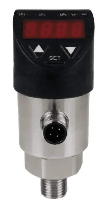
| Compact electronic switch, dual relay, broad range | HM41 | Dual relay with NO and NC contacts, setpoints adjustable across the full range, accuracy selectable from 0.1 to 1 % FS, 4-20 mA option, IP65 |
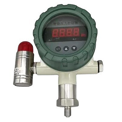
| Digital display, independent window-band trips, high cycle life | 202K | 4-digit LED, two SPDT relays each with its own setpoint and hysteresis, optional 4-20 mA, rated past 1,000,000 cycles |
| Hazardous area | Explosion-proof switch | Certified housing for classified zones |
The HM41 covers a wide span, from a vacuum range down to −100 kPa up to 100 MPa, and carries relays rated for 220 VAC or 24 VDC at 5 A. The 202K leads with its display and per-relay window band, which helps when one device has to hold a low and a high limit at once. Both are browsable from the pressure switches and digital gauges category.
To put a switch on the bill of materials today, work three questions in order:
- Power and simplicity: no power or a single fixed trip points to mechanical; everything else points to electronic.
- Setpoint and deadband: write the trip, the reset, and the gap as a percent of range.
- Output: choose relay, PNP or NPN, or a parallel 4-20 mA to match the PLC card.
Frequently Asked Questions
Does an electronic pressure switch need a power supply?
Yes. An electronic, or digital, pressure switch needs a DC supply, commonly 24 V, to run its sensor, display, and relay logic. A mechanical switch needs no power, which is why it still suits unpowered locations.
What is deadband or hysteresis on a pressure switch?
The deadband is the gap between the setpoint, where the contact trips, and the reset point, where it returns. On a 0 to 10 bar switch set to cut out at 8 bar and cut in at 6 bar, the deadband is 2 bar, or 20 % of range. A wider band stops a pump from short-cycling.
Electronic vs mechanical pressure switch: which lasts longer?
A mechanical snap-action contact rates near one million operations. A solid-state transistor output has no moving contact and effectively no cycle limit, while a relay output sits between them. Match the output to how often the switch will trip.
Can one switch give both a relay output and a 4-20 mA signal?
Yes. Many digital switches, including the HMK 202K, run a 4-20 mA output in parallel with the relay, so one device trips the pump and feeds a continuous reading to the PLC.
How do I wire a PNP versus an NPN switch to a PLC?
A PNP (sourcing) output drives a sinking PLC input; an NPN (sinking) output drives a sourcing input. Confirm the input card type before ordering, or pick a dry relay contact, which suits almost any input.
Specifying a pressure switch for a pump or skid?
Tell us the range, the trip you need, and whether power is available, and we will confirm the deadband, output and HMK model for the job.