Head Mount vs DIN Rail Temperature Transmitter Decision Guide
If you are sitting in front of a P&ID right now with two hundred or two thousand temperature points to specify and your BOM deadline is Friday, here is the short version. Pick head mount when the sensor lives within 100 m of where the signal is needed, the connection head ambient stays under +85 °C, and you want one box to calibrate. Pick DIN rail when the loop crosses long thermocouple runs, you need intrinsically safe entity barriers anyway, or eight or more channels share a cabinet. Form factor changes wiring topology and ownership cost; it does not change accuracy class. The decision matrix below walks the seven lines that actually flip the answer, and we close with two arguments you will hear in the project room that are usually wrong.
The Two Form Factors at a Glance
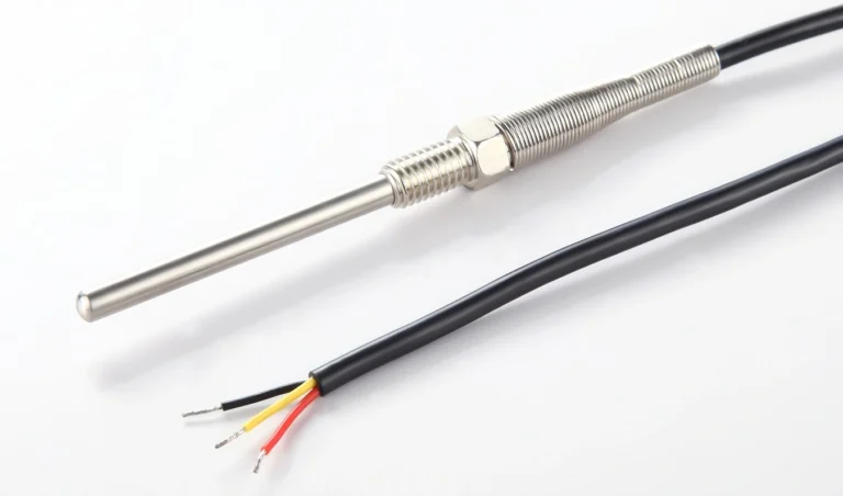
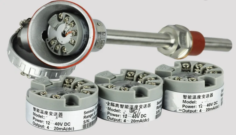
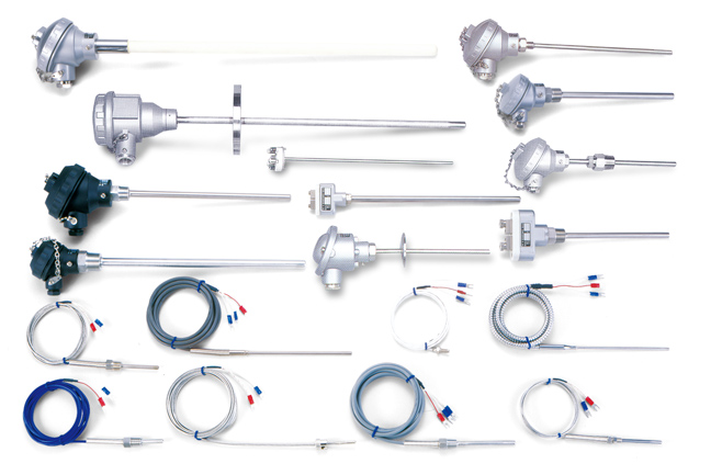
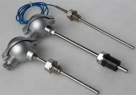
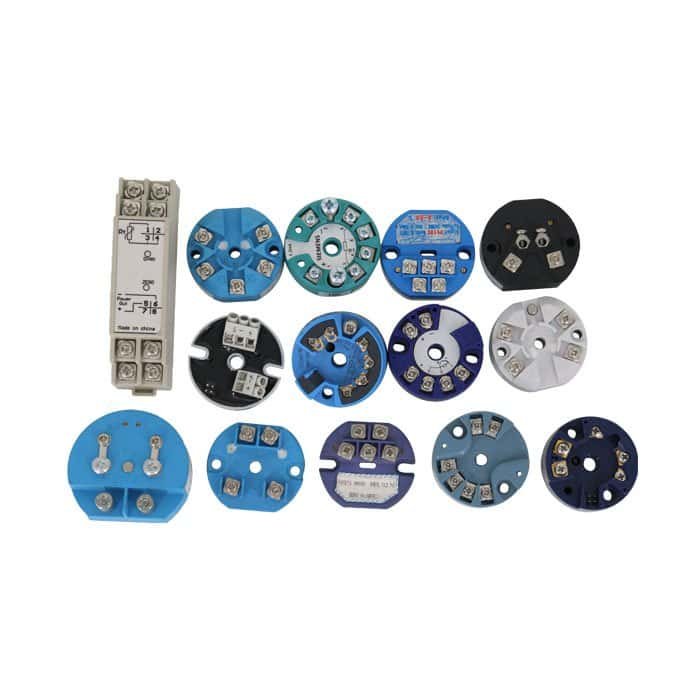
A head mount transmitter is a circular PCB about 44 mm in diameter that bolts inside a DIN form B connection head, the same threaded enclosure (per EN 50446 and DIN 43729) that already sits at the top of an RTD or thermocouple probe. It takes the sensor signal a few centimetres after the wires leave the element and converts it to 4–20 mA right there.
A DIN rail transmitter is a long, narrow brick — usually 22.5 mm wide for single-channel units and 25 mm or 45 mm for dual-channel — that clips onto a 35 mm top-hat rail inside a control panel (EN 60715). The sensor wires travel the full distance from the field probe to the cabinet before any conversion happens.
Older 19-inch rack mount cards still exist on legacy DCS gear, but new projects rarely specify them, so we leave them out of the rest of this guide. The term “field mount transmitter” you see in catalogues from ABB, Yokogawa and others is functionally the same as head mount in this discussion — it describes electronics that live at the probe rather than at the cabinet.
The 7-Line Decision Matrix
We compress the choice into seven criteria. Any single line that tips clearly toward one column tends to dominate the others, so read top to bottom and stop at the first decisive trigger.
| # | Criterion | Head Mount wins when… | DIN Rail wins when… |
|---|---|---|---|
| 1 | Field-to-panel distance | Run is > 30 m, especially with thermocouples (avoid extension wire) | Run is < 10 m or panel-local equipment |
| 2 | Head ambient temperature | Stays inside –40 to +85 °C even with pipe radiation | Pipe surface drives head above +85 °C |
| 3 | Channel density per cabinet | One or two sensors per location | Eight or more channels routed to one cabinet |
| 4 | HART / Profibus PA field config | Engineer needs to clip a HART communicator to the probe locally | All config done from DCS or asset manager |
| 5 | Hazardous area zoning | Whole loop in Zone 1/2, Ex ia entity rating wanted as one assembly | IS barriers already required at cabinet boundary |
| 6 | Access for maintenance | Calibration crew accepts elevated/process-side access (or shutdown windows allow it) | Calibration must be done from cabinet without entering the field |
| 7 | Total wiring cost | Saved cable cost > head mount premium per loop (typically true past 30 m × 4 K-type channels) | Short, dense panel wiring + already-stocked DIN footprint |
Use this table as a checklist. Three or more rows pointing the same direction is decisive; mixed rows are normal and resolved by criterion 7 (cost) most of the time.
Two arguments you will hear in the project room that are usually wrong:
“We always use DIN rail because head mount is too expensive per loop.” True only on short runs with few channels. The moment a loop crosses 30 m with Type K thermocouples, the saved compensation cable closes the gap, and past 60 m head mount usually wins on installed cost even before maintenance enters the picture. We have done this math on three EPC projects in the last two years; once the channel count and run length were honest, DIN rail was the right answer in one of three, not all three.
“Head mount is always more accurate.” Wrong half. Both classes hit the same ±0.1 °C tier on RTD inputs when the silicon is current generation. Head mount’s real advantage is single-loop calibration and freedom from compensation-cable mismatch, both of which matter for long-term drift, not first-day uncertainty. If the customer specifies first-day accuracy on a 5 m run, the panel-side DIN rail card is fine.
When the Sensor Head Is the Wrong Place
Manufacturers spec head mount electronics for ambient bands that cluster between –40 and +85 °C. The HM100 head-mount product page lists a slightly tighter –25 to +80 °C operating window, which is the conservative end of the industry band and is the number to design against if you specify HM100s. Either way the figure is not a marketing number; it sets MTBF.
The trap is that the ambient the spec sheet talks about is the air inside the connection head, not the room. On a 200 °C saturated steam line, the pipe surface easily radiates the lower hemisphere of the head past +90 °C even when room air is +25 °C — over the conservative HM100 limit of +80 °C and approaching the upper-bound +85 °C class. We have seen this on a refinery hot-oil header where six head-mount transmitters drifted up to 0.6 °C inside the first nine months and three drifted further than spec allowed within fifteen months. The fix on that line was straightforward: pull the electronics back to a DIN rail panel 8 m away, leave the probe and its connection head in place, and run shielded thermocouple extension wire between them.
Three field shortcuts let head mount survive higher process temperature without moving to rail:
- A short extension nipple (50–150 mm) between thermowell and head decouples the head from the pipe enough to bring head-air ambient back into spec.
- A reflective sun-shield over outdoor lines knocks a surprising 10–15 °C off head ambient in summer.
- A heat-dissipating connection head (cast-aluminium finned variants) buys another 10 °C of margin compared to plain die-cast types.
Decide criterion 2 from the worst-case head-air temperature, not the room. If you cannot guarantee under the spec’d upper limit (+80 °C for an HM100, +85 °C for most other head-mount classes) with realistic upset conditions, the form factor is already chosen for you.
Calibration Boundaries: Single-Loop vs Split
Calibration uncertainty is where head mount earns its accuracy reputation, and it is the part most generic listicles get wrong.
For a head-mount loop, the sensor (an RTD verified to JJG 229-2010 or a thermocouple to JJG 351) and the transmitter calibrate together as one assembly. A single dry block run produces a single combined uncertainty number. Per the standard’s verification logic, total uncertainty here combines element tolerance, transmitter linearity, and reference-junction or lead-resistance correction in one place.
For a DIN rail loop, the probe travels to one calibration bench, the transmitter to another, and the loop is reconstructed in service. Three small uncertainty contributors stack instead of one:
- Element tolerance (same as above)
- Transmitter linearity (same)
- Lead-resistance match or compensation cable uniformity, characterised on the bench but not the actual installed cable
The two paths can produce numerically similar total uncertainty on paper. The single-loop path is harder to mishandle in the field because there is no cable swap to verify. For loops where long-term stability tighter than ±0.1 °C per year matters — fractionation column overhead temperature is a common one — we prefer head-mount single-loop calibration even when criterion 2 (ambient temperature) is borderline. Cross-check accuracy against NIST ITS-90 reference tables for thermocouple work and IEC 60751 for Pt100 RTD class limits.
The Wiring Cost Math
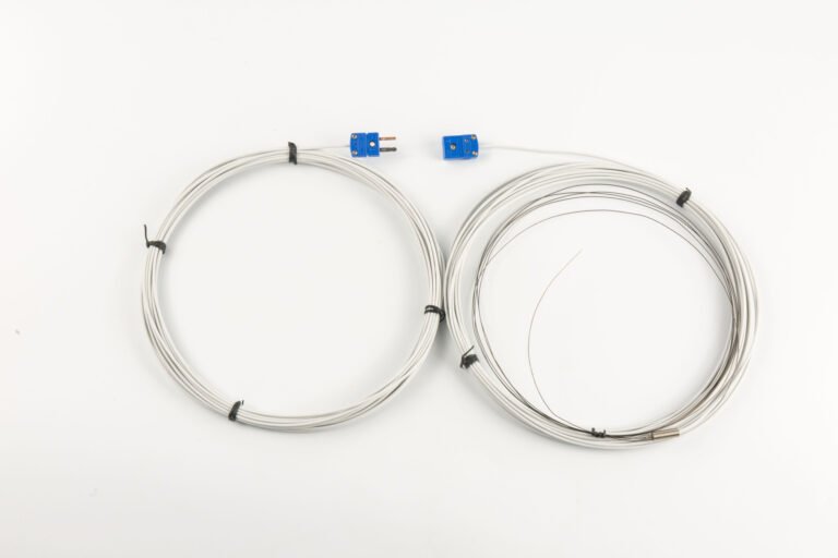
The compensation-wire trap is what flips most long-distance loops to head mount. Type K extension wire (KX grade) or matched compensation cable (KCA grade) runs roughly three times the per-metre cost of generic shielded twisted pair, sometimes higher when small-batch sourced through industrial distributors rather than reel-stock at projects. Per GB/T 11820 industrial temperature transmitter guidance, transmission distances above 200 m are routinely moved to field-mounted (head or remote) electronics specifically to avoid this cost ladder.
The wider the project (more channels, longer runs, more lots of compensation cable to certify), the harder the math swings toward head mount. The opposite is true for small panels with eight channels of RTD wired in 4-wire mode over short distances; there, plain copper of equal quality back to a DIN rail card costs less than ten head-mount conversions.
We are explicit about avoiding currency figures here. Both the absolute cost and the ratio matter; project economics will tell you whether the threshold is four channels or fourteen, and your local cable supplier sets the multiplier.
Hazardous Area, Multi-Point and Maintenance
Three secondary criteria deserve a paragraph each because they tip more loops than the matrix suggests at first reading.
Hazardous area (criterion 5). A head-mount transmitter inside a properly rated connection head (Ex ia IIC T6, IP67 typical) crosses the cabinet boundary as a single certified assembly. A DIN rail transmitter takes the cabinet’s IP and Ex rating, plus a separately certified IS barrier on the field side. Either path works, but the rail-mount path adds a barrier panel, a separate entity-parameter check, and one more certificate to file.
On a chemical plant tank-farm project we worked through, the owner had budgeted for an IS barrier wall — twenty-four channels of Zone 1 temperature heading into the safe-area DCS room. We modeled both paths. Going head-mount with Ex ia certified connection heads removed the need for sixteen of the twenty-four IS barriers (the other eight were shared with pressure and level), shrank the barrier cabinet from a forty-RU rack to a sixteen-RU one, and dropped one full certification cycle off the commissioning critical path. The owner’s electrical engineer initially objected to the change because his standard documentation package assumed rail-mount everywhere; once we walked through the entity-parameter math with him, he agreed to the swap. That is the typical pattern we see — the form-factor decision touches the electrical scope, not just the instrument scope.
Multi-point density (criterion 3). Modern dual-channel DIN rail cards fit two universal sensor inputs in a 22.5 mm slice. Sixteen channels become an eight-card row that is thirty centimetres wide. Sixteen separate head-mount transmitters require sixteen separate probes, sixteen separate connection heads, and sixteen separate field installations. For tray-dryer skin temperatures, packed-bed catalyst beds, and similar multi-element applications, rail mount almost always wins on installation labour.
One pattern we see often: a fixed-bed reactor with twelve thermocouples spread up and down a catalyst bed, each measuring a different axial temperature, all wired to a marshalling cabinet about twenty metres away. Twelve head-mount transmitters mean twelve installations on a small reactor head where space is already tight, and twelve calibration cycles each shutdown. One six-card DIN rail row inside the marshalling cabinet handles the same twelve channels, calibrates in one window per card, and uses thermocouple extension wire on a single multi-pair tray run. Reactor multi-point measurement is one of the clearest cases where rail mount earns its place even though the loop is otherwise distance-friendly.
Maintenance access (criterion 6). Rail-mount replacement is a five-minute job from the front of the cabinet with a screwdriver. Head-mount replacement requires reaching the probe, often with elevation gear or a hot-work permit, and sometimes with a process shutdown if the thermowell is the only mechanical isolation. If your maintenance crew schedules cabinet work on a routine basis but flags field work as a non-trivial event, that operational reality outweighs many of the technical criteria.
How HMK Spans Both Form Factors
HMK currently fields head-mount and panel-style temperature instruments, plus an integrated temperature-and-pressure variant. We are open about the catalogue: a 22.5 mm pure-DIN-rail card is not in our standard line yet, so the closest panel-friendly option from us is the SBW series with a head-separated mounting kit.
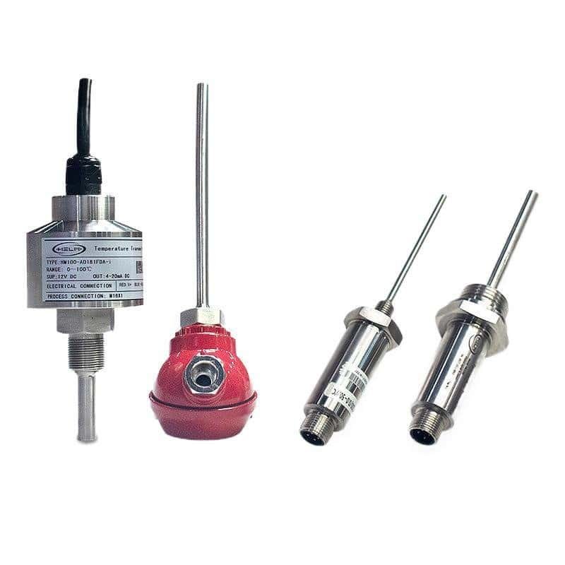
HM100 Temperature Transmitter
Form factor: DIN form B head-mount
Single point, head ambient under +80 °C (HM100 published range −25 to +80 °C), distance over 30 m, HART preferred.
SBW Series Temperature Transmitter
Form factor: Head-mount or panel-separated
When you need DIN rail behaviour but want single-supplier sensor + transmitter calibration chain.
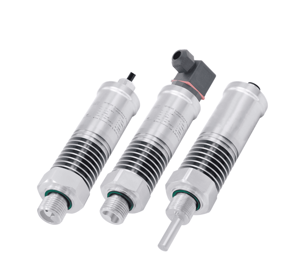
HPTM189 Integrated T+P
Form factor: Head-mount, dual-process
Reactor inlet, compressor discharge, anywhere temperature and pressure share the same tap.
The honest framing: if your project is a panel-dense control building with sixteen RTDs feeding a DCS through a barrier wall, mass-market 22.5 mm rail cards from the usual brands are the natural fit. If your project is field-distributed with 50 m+ runs and you want sensor + transmitter to calibrate as one unit, HMK’s head-mount line is built for that case. See our temperature sensor selection guide for the upstream decision (what sensor element to use) before this form-factor choice.
Frequently Asked Questions
Can I convert a head-mount temperature transmitter to DIN rail?
Most major brands sell adapter cradles that clip a Form B circular PCB onto a 35 mm rail; the HM100 fits a generic Form B adapter from third-party distributors. Convert when control-room electronics need to live in a hostile field location, but check the transmitter vibration spec first because head-mount units are not always rated for cabinet-fan vibration over years.
Does HART work the same on head-mount and DIN rail transmitters?
Yes. HART is a protocol layered on 4–20 mA and is mount-independent. A head-mount HART transmitter and a DIN rail HART transmitter speak identical HART 7 commands. The only practical difference is where you clip the communicator: at the probe head for one, at the cabinet for the other.
Is head mount inherently more accurate than rail mount?
No. Both can hit ±0.1 °C class accuracy on RTD inputs. Head mount tends to drift less in service because the sensor and transmitter share one calibration history and one cable run. That is a system-level advantage, not an electronics-level one.
What ambient temperature kills a head-mount transmitter?
Published specs vary from –25 to +80 °C on conservative classes like the HM100 up to –40 to +85 °C on broader-band models. Sustained operation above the upper-bound +85 °C ages capacitors and accelerates calibration drift; intermittent excursions to +100 °C are survived but log-worthy. Above +120 °C, electronics fail within hours rather than years.
Multi-point: head-mount per sensor or one shared DIN rail card?
For four or fewer points spread over distance, head-mount-per-sensor wins on cable and on calibration. For eight or more points in one cabinet, dual-channel rail cards win on cost density and on cabinet real estate. The crossover sits around five points for most temperate-climate, low-Ex projects we have specified.
About the author — Ye Dong
Temperature Product Engineer · Professor-Level Senior Engineer
40+ years industrial instrumentation; former Deputy Chief Engineer at Sinopec Beijing Design Institute & Sinopec Engineering Construction. Specialises in industrial thermocouple, RTD and temperature transmitter design and field troubleshooting across petrochemical, power, and water-treatment plants. Read more from Ye Dong →
Spec a temperature loop that survives the field
Send us your line conditions — head temperature, distance, channel count, area classification — and we will return a one-page form-factor recommendation with the right HMK SKU.
Related: Once the transmitter is chosen, see how to calibrate a temperature transmitter (RTD & TC) for the sensor-trim versus output-trim procedure.