DP Level Measurement: Principle, Setup & How to Pick (2026)
A DP transmitter tells you a liquid level by measuring weight, not by looking at the surface. Mount it correctly, compensate for density, and it will outlive three rounds of radar gauges in a refinery. Mount it wrong, and the reading drifts until nobody trusts the control room.
Related: wet-leg and dry-leg errors usually start in the piping — see impulse lines for pressure & DP transmitters.
For wells specifically, see our well water level sensor selection guide.
This guide is the setup manual we use when a new storage tank or reboiler comes online. It covers the working principle, the LRV and URV math for the four configurations you will actually encounter, density and temperature errors you have to budget for, and how HMK HM3051DP stacks up against Rosemount 3051S, Yokogawa EJX, and E+H Deltabar on the specs that matter for level. If you are deciding whether DP is still the right call versus radar or guided-wave in 2026, §6 gives you the decision rule.
How a DP Level Transmitter Actually Works
A differential pressure (DP) transmitter has two process connections: a high-side (HP) and a low-side (LP). Each connection sees its own pressure. The transmitter outputs the difference.
DP is one of two field implementations of the same hydrostatic principle (P = ρgh). For the principle hub that also covers the submersible-probe alternative, see our hydrostatic level measurement guide.
For level measurement, you use that difference to compute the hydrostatic weight of the liquid column above the HP tap. The rule is simple:
ΔP = ρ × g × h
where ρ is liquid density (kg/m³), g is 9.81 m/s², and h is the liquid height above the HP tap (m). If ρ and g are constant, h is linear with ΔP, and ΔP is what the transmitter already outputs. That is the whole principle.
The catch is that ρ is only constant in textbooks. In a real tank, ρ changes with temperature, with batch composition, and with entrained gas. Every serious DP level install has to answer three questions. What does the LP side see, what does the HP side see, and what does the density do over the operating envelope. The next three sections answer those in order.
For a refresher on how a DP cell actually generates the ΔP signal electrically, see our DP transmitter working principle article.
The Math: LRV And URV in 4 Configurations
LRV (Lower Range Value) is the ΔP the transmitter reads when the tank is at minimum level. URV (Upper Range Value) is the ΔP at maximum level. Spanning the transmitter means telling it what 4 mA should be (LRV) and what 20 mA should be (URV). Get this math wrong and the loop is off from day one.
The four configurations below cover close to every real install. Worked examples use density ρ = 850 kg/m³ (a mid-grade diesel or heavy naphtha) and gravity g = 9.81 m/s² = 9.81 kPa/m of water-equivalent, scaled by SG.
Open tank (vented to atmosphere)
Both sides see atmospheric pressure; the LP tap is left open to vent. The HP tap sits at the bottom of the tank. The height above the HP tap is h.
- LRV = 0 kPa (tank empty at the tap)
- URV = ρ × g × H_max = 850 × 9.81 × 10 / 1000 = 83.4 kPa for a 10 m tank
This is the easy case. No migration, no wet leg, no surprises.
Closed tank, dry leg
The tank is pressurized (e.g. nitrogen blanket). The LP tap sits above the maximum liquid level and is connected by a dry impulse line to the LP side of the transmitter. The LP line fills with the same gas at the tank head pressure, so the static head on both sides cancels. The transmitter reads only the liquid column.
- LRV = 0 kPa
- URV = ρ × g × H_max (same as open tank)
Dry legs work when the vapor is clean and non-condensing. If condensate accumulates in the LP line, the “dry” leg becomes a partial wet leg and the reading drifts. This is the #1 field failure mode for dry-leg installs.
Closed tank, wet leg (HP elevated above tap)
The LP line is intentionally filled with a known fill fluid such as glycerin, silicone oil, or inhibited glycol (see table below). The wet leg creates a constant negative offset on the LP side. The transmitter has to be zero-elevated (range suppression) to compensate.
Let H_LP = height of wet-leg fluid column above LP tap, ρ_fill = fill fluid density. Then:
- LRV = − ρ_fill × g × H_LP (negative because LP > HP when tank is empty)
- URV = ρ_liquid × g × H_max − ρ_fill × g × H_LP
Worked: tank H_max = 10 m, H_LP = 10 m, ρ_liquid = 850, ρ_fill (glycerin 1:1 with water) = 1140 kg/m³.
- LRV = − 1140 × 9.81 × 10 / 1000 = − 111.8 kPa
- URV = 83.4 − 111.8 = − 28.4 kPa
Span = URV − LRV = 83.4 kPa. Note the span stays the same as the open-tank case; what changes is the elevation point. A smart DP transmitter with remote zero and range lets you set that migration digitally rather than re-piping.
Fill-fluid selection table (sourced from Chemical Industry Press, “Industrial Instruments and Automation Devices” handbook 2019 ed., and the Gongkong.com field-tech database):
| Fill fluid | SG @ 20°C | Usable T range (°C) | Vapor pressure | Best for |
|---|---|---|---|---|
| Glycerin 50% in water | 1.14 | −15 to +90 | Low | Ambient pressurized tanks |
| Silicone oil 200/50 cSt | 0.97 | −40 to +200 | Very low | Hot process, wide-range temp |
| Inhibited ethylene glycol 50% | 1.07 | −40 to +110 | Moderate | Cold climates, outdoor tanks |
| Process liquid (self-fill) | varies | ambient only | varies | Low-cost, non-volatile media |
| Halocarbon 4.2 (Galden HT) | 1.88 | −30 to +230 | Very low | Oxidizer service, high-T refinery |
Most English datasheets list only silicone and halocarbon. The glycerin and ethylene-glycol lines are common in Chinese refinery specs because they survive winter in north China without trace heating.
Closed tank, wet leg with condensate pot
In steam or hot-vapor service, the LP line fills naturally with condensate. A condensate pot is welded to the vessel at the same elevation as the LP tap. It keeps the LP column at a constant height even as the tank level changes. The math is the same as the wet-leg case. What the condensate pot gives you is a mechanical guarantee that H_LP stays fixed.
Chinese Sinopec design rules (standard HG/T 20507-2014) require the condensate pot on any DP level loop where vapor saturation exceeds 150°C. Missing pots are a common reason English-source “just install a wet leg” advice fails on refinery hot towers.
Regulatory note: JB/T 9329-2015 (the Chinese machinery industry standard) specifies the range-migration rules Chinese chemical plants audit against. If your commissioning documentation does not show the migration calculation, expect to redo it before HSE signs off.
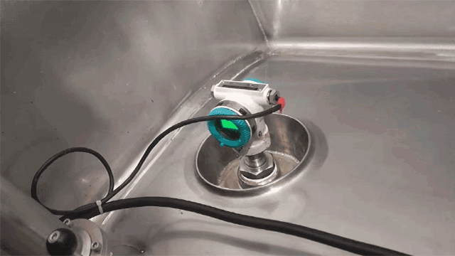
4 Mounting Configurations With Diagrams
Where you put the transmitter relative to the tank determines 80% of the measurement error budget. These are the four you will actually see.
A. Tap at tank bottom, transmitter at tank bottom
Simplest, cheapest, fewest errors. Only works on open tanks where condensation and freezing are not a concern. Impulse line from HP tap to transmitter runs horizontal and short (< 2 m). LP side vented.
B. Tap at tank bottom, transmitter below the tap (HP elevation)
When the transmitter has to drop below the tap (e.g. mounted at grade level under an elevated tank), the HP impulse line gains its own hydrostatic head. That adds a constant offset to every reading. Zero the transmitter in-situ with the tank at a known level; do NOT compensate in the DCS.
C. Tap at tank top, transmitter at tank top (closed tank, dry leg)
Standard pressurized-vessel arrangement when the process gas is dry. LP tap is at the top of the tank vapor space; HP tap is at the bottom. Impulse lines must slope back toward the tank at 1:12 minimum, per the Sinopec Design Institute DP installation standard. A line that slopes toward the transmitter pockets condensate and drifts the reading on every cold morning.
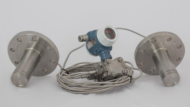
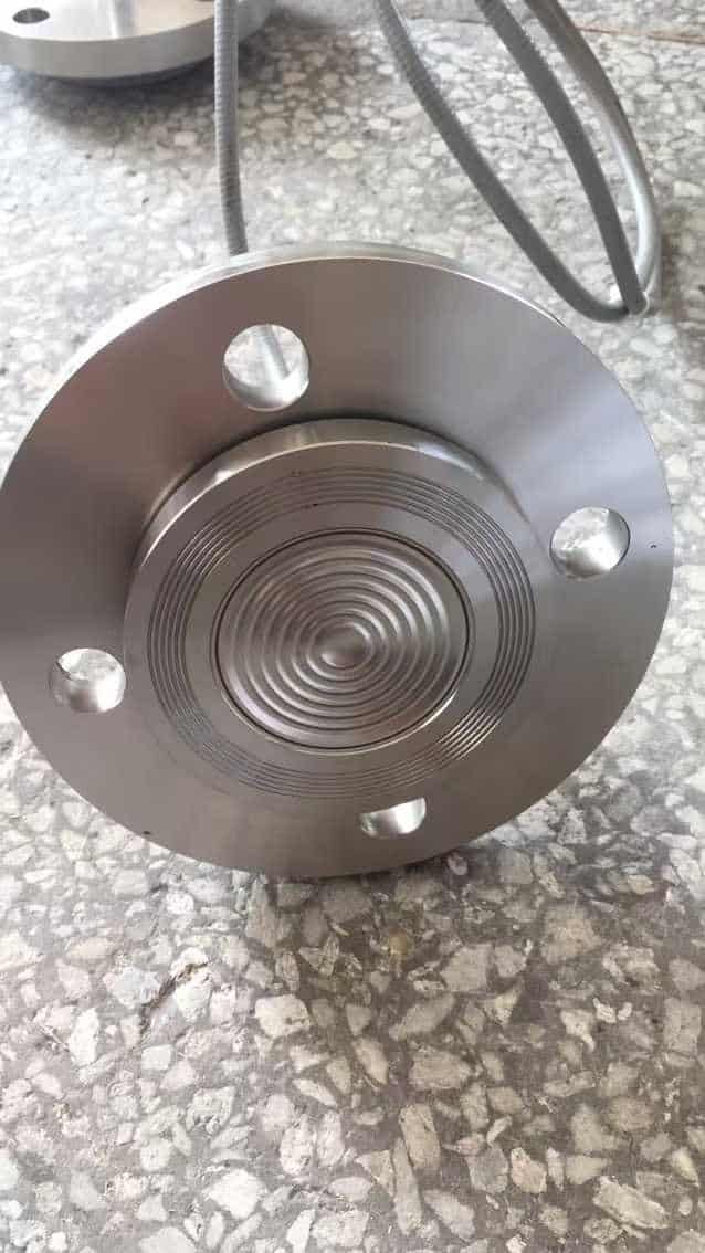
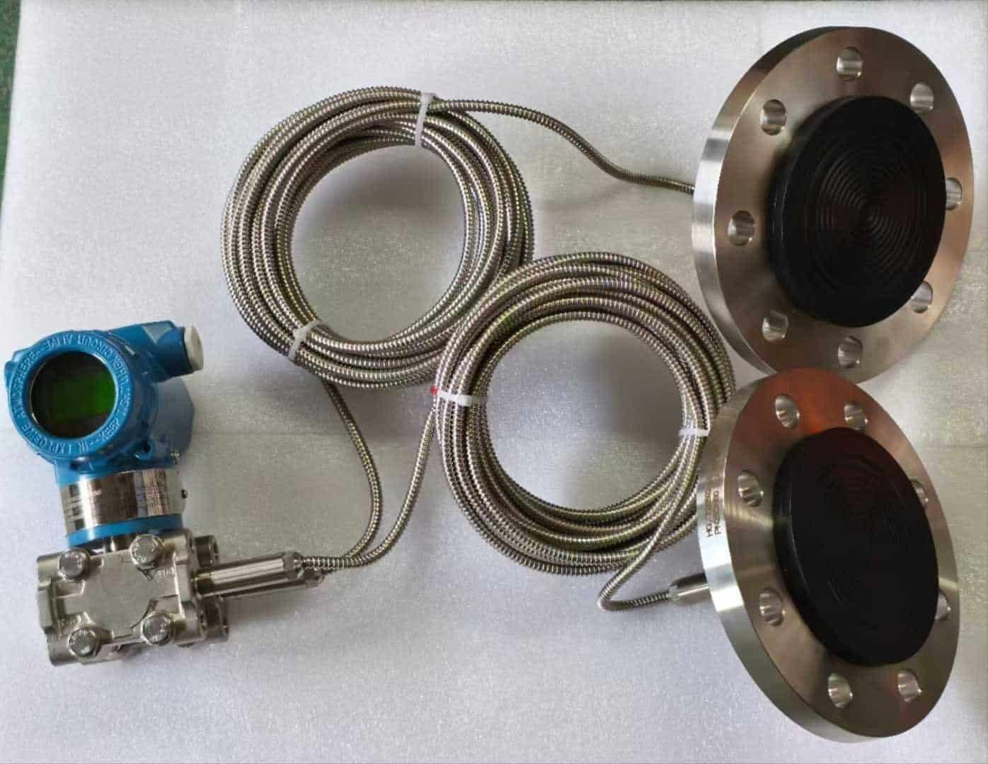
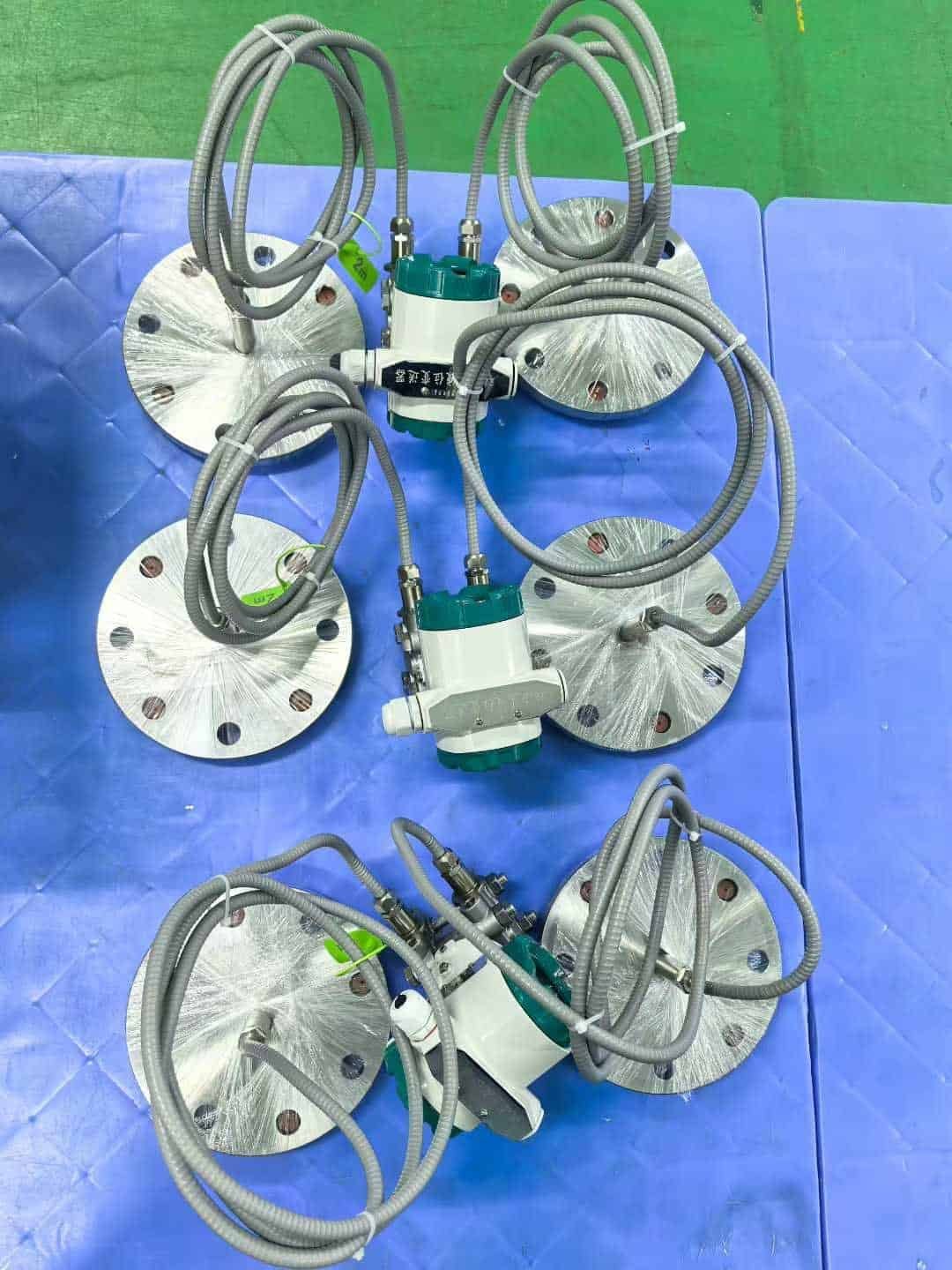
D. Remote seals on both sides (wet-seal DP)
For molten sulfur, slurry, glass-lined acid service, or any media where impulse lines would plug or freeze, use remote seals. Diaphragm seals mount at the HP and LP taps; capillaries filled with silicone oil (or DC704 for hot service) carry the signal to the transmitter. This eliminates impulse lines but introduces capillary temperature error, covered in §4.
Four install errors that kill 90% of new DP level loops (from a 2023 Maoming Refinery commissioning review):
- LP line not sloped correctly. Condensate pockets in “dry” legs shift the zero every temperature cycle.
- Transmitter vent valves not purged at commissioning. Trapped air on one side creates a false ΔP that looks like level.
- Wet-leg fill fluid density not documented. Two years later, nobody knows whether it was glycerin or silicone, recalibration becomes guesswork.
- Tap isolation valves closed during operator rounds. Accidental closure freezes the reading at the last good value. Control room thinks the tank is stable while it is overflowing.
Density Drift And Temperature: The Two Silent Errors
A DP transmitter reports ΔP to ±0.065% of span. That is the spec you see on the datasheet. The level error you actually care about is usually 5–10× worse. Where does the rest come from? Density drift and temperature.
Density drift
The equation is h = ΔP / (ρ × g). If you calibrate at ρ = 850 kg/m³ but the tank actually holds 820 kg/m³, the reported level is off by 3.7% even with a perfect transmitter. Over a 10 m tank that is 37 cm of error. Over a 20 m crude tank that is over 70 cm, enough to trigger a false high-level alarm.
Field data from a Maoming Refinery atmospheric-plus-vacuum distillation DP level loop, measured over 18 months:
| Date | Batch | Measured ρ (kg/m³) | Calibrated ρ | Level error at 60% fill |
|---|---|---|---|---|
| 2024-03 | Light naphtha | 695 | 720 | +2.1 m high |
| 2024-08 | Heavy gas oil | 885 | 850 | −0.5 m low |
| 2024-11 | Crude blend A | 870 | 850 | −0.2 m low |
| 2025-02 | Heavy gas oil | 878 | 850 | −0.4 m low |
Three ways to handle this:
- Accept the error if the tank serves an intermediate buffer and ±5% is fine.
- Density compensation via DCS. Read temperature at the tank and a density reference curve into the level calculation. This is what modern Honeywell Experion and Emerson DeltaV do out of the box; you provide the ρ(T) table.
- Install a parallel density meter (online Coriolis or nuclear). Overkill for most tanks, but standard on custody-transfer storage.
Temperature on the transmitter body
Temperature affects the transmitter itself, not just the liquid. Every 10°C change in ambient shifts the zero by roughly 0.05% of span (ISA-S51.1 figure; Rosemount, Yokogawa, and Endress all quote ± 0.08% per 28°C, the same number in different packaging). On an outdoor install where day/night swing is 25°C, that is 0.125% of span drift on ambient alone.
Remote-seal installs are worse. The silicone oil in the capillaries expands with ambient. A 50-m capillary on an asphalt tank in summer can add 2–3% of span of apparent level. Chinese instrumentation standard JJG 882-2019 requires seasonal recalibration on any remote-seal DP loop over 30 m capillary, a step most English commissioning procedures skip.
Practical rule: If you can’t shield the capillaries from direct sun, add at least 0.8% of span to your accuracy budget.
Remote Seals Vs Direct Mount: When Each Wins
Direct mount (impulse-line piping) is the default. Remote seals exist because impulse lines can’t handle some media.
Pick direct mount when:
- The media stays liquid at ambient and doesn’t freeze
- Impulse lines can be drained and purged without plant shutdown
- Operating temperature at the tap is under 150°C
- Media is clean enough that lines won’t plug
Pick remote seals when:
- Media is a slurry, molten, cryogenic, or highly corrosive
- Media will vaporize or condense in an impulse line
- Tap elevation forces capillaries over 3 m long
- The tank is on a TEMA Class II or higher service (refinery hot towers, HDS reactors)
The failure mode people underestimate on remote seals is seal fluid ingress. If the diaphragm develops a pinhole, silicone oil enters the process. On a food/pharma tank this is a recall event. Ceramic or tantalum diaphragms extend life in acid service; gold-plated Hastelloy C276 is the standard for chlorides. HMK HM3051DP offers Hastelloy C, 316L, Monel, and tantalum as diaphragm options. See the HM3051DP product page for media compatibility details.
DP Vs Radar Vs Guided Wave: When DP Is Still The Right Call
Radar (FMCW) and guided-wave radar (TDR) have chipped away at DP level market share for 15 years. For 2026, the decision rule is:
| Scenario | DP | Radar | Guided wave |
|---|---|---|---|
| Clean liquid, stable density, closed tank | ✓ Best TCO | OK | OK |
| Variable density batch processing | ✗ | ✓ | ✓ |
| Foaming or turbulent surface | ✓ | ✗ | △ |
| Cryogenic (LNG, LIN) | △ | △ | ✓ |
| Interface measurement (oil-on-water) | ✓ | ✗ | ✓ |
| Capex budget tight | ✓ | ✗ | ✗ |
| Custody transfer | △ | ✓ | ✓ |
Three things still favor DP:
- Price. A fit-for-purpose DP loop (transmitter + impulse piping + install) costs under half of a comparable 80 GHz radar install on anything taller than 6 m.
- Foaming service. Surface-reflecting methods (radar, ultrasonic) lose signal on foam. DP reads the weight of the column regardless of what the surface looks like.
- Interface measurement. Two immiscible liquids with different SGs produce a ΔP proportional to interface height. DP is the only technology that gets this measurement for free.
The honest failure case for DP is variable density. If you process 10 different batches with different SGs and can’t measure density inline, radar or guided wave is the right call.
Spec Comparison: HMK HM3051DP Vs Rosemount 3051S, Yokogawa EJX, E+H Deltabar
Level-relevant specs only. Full comparison for general DP service is in the DP working principle article.
| Spec | HMK HM3051DP | Rosemount 3051S | Yokogawa EJX118A | E+H Deltabar PMD75B |
|---|---|---|---|---|
| Accuracy | ±0.065% of span | ±0.025% of span (Ultra) | ±0.04% of span | ±0.05% of span |
| URL | 25 kPa – 25 MPa | 62 Pa – 68 MPa | 100 Pa – 32 MPa | 50 Pa – 40 MPa |
| Turndown | 100:1 | 200:1 | 200:1 | 100:1 |
| Diaphragm materials | 316L, Hastelloy C, Monel, Tantalum | 316L, Alloy C-276, Tantalum, Gold-plated | 316L, Hastelloy, Monel, Tantalum | 316L, Alloy C-276, Tantalum, Gold |
| Remote seal max capillary | 30 m | 30 m (50 m special) | 30 m | 30 m |
| Output | 4–20 mA HART 7, Profibus PA, FF | 4–20 mA HART 7, Profibus, FF, WirelessHART | 4–20 mA HART 7, BRAIN, FF | 4–20 mA HART 7, Profibus, FF, Bluetooth |
| Ambient temp error | ± 0.08% per 28°C | ± 0.075% per 28°C | ± 0.08% per 28°C | ± 0.08% per 28°C |
| SIL | SIL 2 (1oo1), SIL 3 (1oo2) | SIL 2, SIL 3 (1oo2) | SIL 2 | SIL 2, SIL 3 (1oo2) |
| Warranty | 3 years | 2 years | 2 years | 2 years |
| Budget (new, HART, no seals) | $$ | $$$$ | $$$ | $$$ |
What the numbers say:
- If you need sub-0.03% accuracy for custody transfer, the Rosemount 3051S Ultra is the reference. Nothing else matches on paper.
- For general refinery level work (accuracy ±0.1% is fine, SIL 2 is required), HM3051DP lands within 0.05% of the European brands at roughly 40–60% of the price. Over a 50-tank install, that is a material capex difference.
- Yokogawa EJX holds zero best when your span has to move frequently. It is the turndown-at-zero story in this group.
- E+H Bluetooth commissioning on the PMD75B saves one trip up the tank ladder per instrument. Worth paying for on tall offsite storage.
For HMK-specific DP part numbers, wetted-parts options, and datasheet, see the HM3051DP product page.
Pre-Commissioning Checklist (Refinery Version)
This is the list our team runs before energizing a new DP level loop. Skipping any of these lines is what creates the “brand new instrument already drifting” phone call.
Mechanical
- HP and LP impulse-line slope: minimum 1:12 back toward the tank. No sags.
- Tap isolation valves: full-open, handles tagged “DO NOT CLOSE — level loop”.
- Vent-plug torque on transmitter head: per manufacturer spec, 20–25 Nm for most models.
- Manifold bleed screws: 5-valve manifold preferred for any pressurized service.
- Remote-seal capillaries: shielded from direct sun; insulated on hot service.
Electrical
- Loop resistance: verified against 24 VDC supply capacity (≥ 250 Ω required for HART comms).
- Shield grounded at one end only (DCS side, not transmitter).
- EMI conduit separation from VFD cables: minimum 300 mm.
- Loop current: verify 4 mA reading at LRV, 20 mA at URV with known calibrated input.
Configuration
- Spanning: LRV and URV entered match §2 calculation for the actual configuration.
- Engineering units in DCS: consistent with transmitter (kPa, mmH₂O, or m — pick one, document).
- Damping: 0.5–2 s for stable tanks, 2–5 s for agitated service.
- Alarm limits: high, high-high, low, low-low each set with at least 5% deadband.
- HART tag and long tag: written into asset management system before energizing.
Documentation
- Range migration calc (per JB/T 9329-2015): filed with loop drawing.
- Fill-fluid type and density (if wet leg): written on loop sheet, not just in a vendor spec.
- Density compensation reference curve (if applicable): loaded in DCS.
- First post-commissioning calibration scheduled: 30 days post-startup, not annual.
For wiring the 4–20 mA loop itself, see our 4-20mA pressure transmitter wiring guide. For HART-specific network topology, see HART vs 4-20mA.
For saturated steam service, where the water and steam density both shift with drum pressure, see our dedicated guide on boiler drum level measurement.
On tanks with aggressive or plugging media, feeding the DP cell from a bubbler dip-tube keeps the wetted parts inert.
Frequently Asked Questions
Mount the HP connection at or below the minimum liquid level, and the LP connection either open to atmosphere (open tank) or at the vapor space (closed tank, dry leg) or connected to a wet leg. Calculate LRV and URV from the liquid density and the tank geometry using ΔP = ρ × g × h, span the transmitter accordingly, and pipe 4–20 mA output to the DCS. See §2 and §3 above for the four standard configurations.
A DP (differential pressure) level transmitter is a pressure sensor with two process connections whose output is the difference between them. When those connections are piped to the high and low points of a liquid column, the ΔP is proportional to the height of the column (via hydrostatic pressure), and the transmitter effectively reports level. It is one of the oldest and still one of the most reliable level technologies in continuous process service.
Interface measurement uses a DP transmitter to find the boundary between two immiscible liquids of different densities (e.g. oil sitting on water in a separator). Because ΔP across the interface is proportional to (ρ_water − ρ_oil) × g × h_water, the transmitter can resolve how much of the column is water and how much is oil. This is one of the few measurements where DP still beats radar and guided-wave, because neither of those sees a density interface directly.
Four technologies dominate: differential pressure (DP), radar (FMCW or pulse), guided-wave radar (TDR), and hydrostatic (single-sided pressure). DP and hydrostatic submersible level transmitters use weight; radar and guided-wave use surface reflection. DP wins on foaming service, interface measurement, and capex. Radar wins on variable-density batch processing. Guided wave is the bridge between them. The decision table in §6 gives a per-scenario recommendation.
LRV is the ΔP at minimum measurable level, the value that maps to 4 mA on the output. URV is the ΔP at maximum level, mapping to 20 mA. The difference URV − LRV is the span. LRV is not always zero: in a wet-leg closed-tank install, LRV is a negative number because the LP side sees more pressure than HP when the tank is empty. Setting the correct LRV is what people mean by “zero elevation” or “zero suppression” on the configuration form.
To sanity-check your LRV/URV math, plug ΔP and SG into our pressure to liquid level calculator — it inverts h = P / (ρ·g) with four pressure-unit inputs and four depth-unit outputs in one step.
Hydrostatic level is one of three classic DP-transmitter applications. The other two are pressure measurement and flow — see the DP flow measurement guide for the orifice / venturi / V-cone primary elements that turn the same transmitter into a flow meter.