Pressure Sensor vs Transducer vs Transmitter: A Three-Axis Decision Framework (2026 Guide)
A pressure sensor is the umbrella term for any device that converts pressure into an electrical signal. A pressure transducer outputs a conditioned but unamplified voltage signal (typically 0–5 V, 0.5–4.5 V, or 1–5 V) and responds fast enough for dynamic measurements. A pressure transmitter adds signal conditioning and a 4–20 mA current output built for long cable runs and industrial noise.
That’s the textbook answer every competitor gives. But the name on the datasheet isn’t what you should pick on. Keep reading — we’ll show you a three-axis framework that tells you exactly which one your application needs, backed by three real projects we’ve shipped to Europe, Singapore, and the US.. When you have settled the device category and need a tighter accuracy spec, the precision pressure sensor guide covers the 0.1 % FS line that separates precision from standard grade.
Why the Names Confuse Everyone (Including Manufacturers)
Here’s the honest truth most suppliers won’t tell you: the industry uses these three terms inconsistently. WIKA, TE Connectivity, Ashcroft, and Setra each draw the lines slightly differently. Some vendors sell a 4–20 mA unit and call it a “transducer.” Others sell a 0–5 VDC unit and call it a “transmitter.” The terminology is fuzzy because the underlying technology is a spectrum, not three discrete buckets.
The good news: you don’t need to win the terminology argument to make a good purchase. What matters for your application is the electrical behavior of the device, not what the brochure calls it. In fifteen-plus years of shipping custom pressure instruments, we’ve found almost every selection decision comes down to three physical conditions:
- How far does the signal travel from the sensing element to your data logger or PLC?
- How fast does the pressure change that you need to capture?
- How is the device powered, and how does that fit your control architecture?
We call these the three axes. Once you place your application on each axis, the right product type is obvious — regardless of what anyone calls it.
Axis 1 — Transmission Distance (Where the 4–20 mA Myth Comes From)
Voltage outputs are fine — right up until they aren’t. A 0–5 VDC transducer used within 5 meters of a data acquisition card will give you a clean, accurate reading. Push that cable run to 30 meters in a noisy factory and you’ll see two failure modes at once: the copper resistance drops a measurable share of your signal, and the long cable acts as an antenna for every VFD, motor contactor, and switching power supply nearby.
Current loops solve both problems in one move. In a 4–20 mA loop, the transmitter adjusts its drive voltage to maintain the target current regardless of cable resistance, so a 500-meter run and a 5-meter run read the same value. The low-impedance current loop is also dramatically less susceptible to electromagnetic interference than a high-impedance voltage signal. That’s why process industries standardized on 4–20 mA in the 1970s and haven’t moved off.
The practical rule we use:
- Cable run under ~20 m in a clean environment → voltage output (transducer or raw sensor) is fine and cheaper.
- Cable run over ~20 m, or any path crossing a motor control center → specify a 4–20 mA transmitter. The premium is small and the headache avoided is large.
- Going over 500 m or across plants → transmitter with HART or digital bus, not analog at all.
Distance alone eliminates roughly half the confusion around these three product categories.
Axis 2 — Response Frequency (The Axis Nobody Talks About)
This is where most articles stop and most selection mistakes happen. A pressure transmitter with its full signal conditioning chain has a built-in damping effect. The amplifier stage, filtering capacitors, and 4–20 mA driver together give you excellent stability on a slowly changing process pressure — but they also cap the frequency response, typically under 100 Hz for analog transmitters and sometimes as low as 10 Hz when heavy damping is enabled. That’s perfect for a boiler header or a storage tank. It’s useless for a shock wave.
A transducer or raw pressure sensor, without the 4–20 mA conversion stage, can respond in the kilohertz range. High-specification dynamic sensors go well into the hundreds of kilohertz.
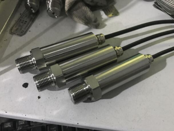
Case 1 — European hydraulic vibration test rig, 0–20 kHz dynamic pressure. A European R&D lab came to us after their first supplier’s 4–20 mA transmitter turned their dynamic pressure spikes into a smooth, uninformative line. We built a custom high-frequency transducer: 0–400 bar range, 0–5 VDC output for kilohertz-band capture, M20×1.5 thread with 10 mm engagement, AISI 316 wetted parts for the mildly acidic cleaning fluid, rated to 80 °C. The rig engineer got the real waveform on the first calibration run. They’ve since reordered 20 units for additional test cells.
The rule here is blunt. If the pressure you care about changes faster than a few times per second — water hammer, pulsation, combustion, hydraulic shock, injection events — a transmitter is the wrong tool. You need a transducer or a dedicated dynamic sensor, and the output needs to be voltage or IEPE, not a 4–20 mA loop that physically cannot slew that fast.
Axis 3 — Power Architecture (Loop-Powered vs Externally Powered)
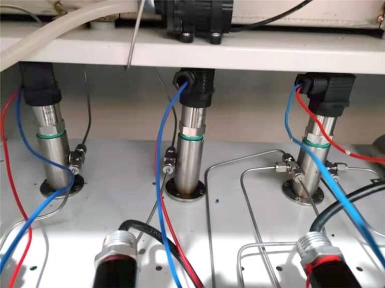
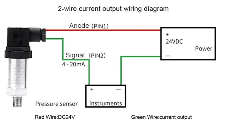
The third axis is often overlooked during spec writing and remembered painfully during installation. A 4–20 mA transmitter is almost always two-wire loop-powered: the same pair of wires carries the 24 VDC supply and the measured signal. That’s elegant in the field — less wiring, simpler terminations, straightforward intrinsic safety barriers for hazardous areas.
A transducer or sensor typically uses three or four wires: a dedicated supply (5 V, 10 V, or 24 V), a signal line, a common ground, and sometimes a shield. The wiring cost is higher, but the architecture gives you independent power regulation, which matters for very high accuracy and for battery-powered field equipment.
Case 3 — US hydraulic oil pump test bench, 150 MPa. A US test-bench builder specified a pressure transmitter for their high-pressure pump qualification stand: 0–150 MPa range, 4–20 mA output loop-powered from 24 VDC, 0.5 % accuracy, G1/2 B process thread, −20 to 80 °C ambient, no local display needed. Every one of those choices is driven by the power and control architecture: the stand’s PLC expected a 4–20 mA loop, the cabinet had 24 VDC available, and the whole test cell was already wired for two-wire transmitters. A 0–10 V transducer would have forced a separate power supply, additional signal conditioning at the PLC, and a rewiring job. The transmitter dropped straight in.
The rule: if the receiving device (PLC, DCS, data logger) speaks 4–20 mA natively and the cabinet has 24 VDC, the transmitter is the path of least resistance. If you’re building a lab rig with an independent DAQ and a regulated bench supply, a transducer gives you more flexibility and usually better raw signal fidelity.
The Decision Matrix — Read Off Your Choice in 30 Seconds
Map your application onto the three axes, then read across:
| Your Application | Distance | Frequency | Power | Best Fit |
|---|---|---|---|---|
| Storage tank level, central control room | Long (>50 m) | Static | 24 VDC loop | Transmitter (4–20 mA / HART) |
| Hydraulic shock test, lab bench | Short (<10 m) | Dynamic (kHz) | Bench supply | Transducer (0–5 V) |
| OEM machine with onboard PLC | Medium (10–30 m) | Slow (<10 Hz) | 24 VDC loop | Transmitter |
| R&D combustion pressure study | Short | Very dynamic (>10 kHz) | Dedicated supply | Dynamic sensor / transducer |
| Water treatment, field mounted | Long | Static | 24 VDC loop, IP65 | Transmitter with HART |
| Calibration lab reference | Short | Static | Regulated bench | Transducer (ratiometric) |
If your application falls neatly into one row, you’re done. If two rows pull you in different directions — for example, long cable but dynamic signal — that’s the “gray zone,” and you either compromise on one axis or commission a custom build. Which brings us to the third case.
Side-by-Side Specs: Three Real Hammok Projects
The three projects in the table below each sit at a different corner of the three-axis framework. They are real customer builds, with specifications reproduced from the shipped units.
| Parameter | Case 1 — EU Hydraulic Vibrator | Case 2 — SG Low-Pressure Water Lab | Case 3 — US Oil Pump Test Bench |
|---|---|---|---|
| Region / Industry | Europe, R&D / hydraulic testing | Singapore, water research | United States, pump manufacturing |
| Pressure range | 0–400 bar | 10 Pa – 100 kPa | 0–150 MPa |
| Medium | Weak acidic cleaning fluid | Water | Hydraulic oil |
| Temperature | up to 80 °C | 10–25 °C | −20 to 80 °C |
| Frequency demand | 0–20 kHz dynamic | 1–2 MHz natural frequency | Static |
| Output signal | 0–5 VDC | Customer-flexible: 4–20 mA / 1–5 V / 0–5 V | 4–20 mA |
| Thread / Mount | M20×1.5, 10 mm engagement | M20×1.5 | G1/2 B |
| Wetted material | AISI 316 | 316 stainless diaphragm | 316 stainless |
| Power | External bench supply | Depends on chosen output | 24 VDC loop-powered |
| Category on the axes | Transducer | Gray zone (leaning transducer) | Transmitter |
| Outcome | Passed first calibration; customer reordered 20 units | Delivered three output variants in one housing | Dropped straight into existing 4–20 mA cabinet |
Case 2 is the interesting one. The natural frequency requirement (1–2 MHz) is firmly in transducer territory, but the customer accepted three output options because their application spanned both bench calibration and a production data logger. We shipped a unit with selectable outputs so the same hardware could run in both modes. That flexibility is a reminder: when your axes disagree, custom engineering is usually cheaper than buying two instruments.
Common Misconceptions
Is a pressure transmitter just a more expensive transducer?
No. A transmitter includes linearization, temperature compensation, and a 4–20 mA current driver that a bare transducer does not. The extra circuitry is what makes it robust at distance — not a markup.
Can I replace a 4–20 mA transmitter with a 0–5 V transducer to save cost?
Only if your cable run is short, your electrical environment is clean, and your receiving device accepts voltage. In most industrial installations the answer is no — the install cost of running a clean voltage signal offsets any savings on the sensor.
Does output type affect accuracy?
The conversion stage adds a small error budget, but in practice a good 0.1 % transmitter and a good 0.1 % transducer read the same truth. Accuracy is driven by the sensing element and calibration, not the output format.
Why do some vendors call their 4–20 mA products “transducers”?
Because the term “transducer” technically means any energy-converting device. It’s not wrong, just ambiguous. Read the datasheet’s output specification, not the product name.
Choosing Hammok — When Off-the-Shelf Won’t Cut It
Two of the three cases above are fully custom builds. The third is a semi-custom order from our standard transmitter family. That mix is representative of what we do: we carry a full range of standard 4–20 mA pressure transmitters for mainstream industrial use, and we build custom sensors and transducers when the three axes put you in the gray zone — high dynamic frequency, unusual process connection, aggressive media, extreme pressure, or non-standard output.
Our envelope covers 10 Pa to 200 MPa full-scale ranges, M20×1.5 / G1/2 / NPT / custom threads, 316 SS and AISI 316L diaphragms as standard with Hastelloy and tantalum on request, and output options including 4–20 mA, 4–20 mA HART, 0–5 V, 0–10 V, 1–5 V ratiometric, and high-frequency voltage for dynamic applications up to the low-MHz band.
If your application sits cleanly on one row of the decision matrix, our standard pressure transmitter series will handle it out of the box. If you’re in the gray zone, send us the specs below and an engineer will reply within one business day with a recommended configuration — no account or commitment required.
Get a free engineer review of your application
Tell us your pressure range, target output, and application. Our engineers will reply within one business day with a recommended configuration — no account required.
FAQ
Do I need a transmitter if my cable run is less than 10 meters?
Usually no. A 0–5 V or 0–10 V transducer delivers the same accuracy at short distances and costs less. Go to a transmitter when you exceed 20 m, pass near variable-frequency drives, or need to enter a hazardous area with intrinsic safety.
Which is more accurate, a transducer or a transmitter?
Neither category wins by default. Both can be specified at 0.5 %, 0.25 %, 0.1 %, or better. Focus on the accuracy number on the datasheet, not the product category.
Can I use a transducer with a PLC that only accepts 4–20 mA?
Yes, through an external signal converter, but the converter adds error and another point of failure. If the PLC speaks only 4–20 mA, buying a transmitter in the first place is cleaner.
What’s the typical cost difference between a transducer and a transmitter?
For the same pressure range and accuracy, a 4–20 mA transmitter generally costs 15–40 % more than a 0–5 V transducer because of the added signal conditioning. On a project basis, that delta is often smaller than the cost of the extra wiring and shielding a voltage signal would need.
Are pressure sensors and pressure transducers the same thing?
“Sensor” is the umbrella term. A transducer is a type of sensor that delivers a conditioned voltage output. All transducers are sensors; not all sensors are transducers.
Related reading: For temperature-side selection logic, see our guide on how to select an industrial temperature sensor. Browse the full pressure sensors & transmitters catalog for all HM-series options.
Reviewed by Lin Jun (林俊) — Pressure Product Engineer
The pressure selection framework in this article was reviewed by Lin Jun, HMK-TECH Pressure Product Engineer and Senior Process Instrumentation Specialist. Lin Jun graduated from the Automation Department of China University of Petroleum in 1989 and has over 35 years of hands-on experience designing process instrumentation for refineries and petrochemical plants — including crude distillation, catalytic cracking, hydrocracking, delayed coking, and sulfur recovery units. His expertise spans diffused silicon, ceramic capacitive, sapphire, and MEMS pressure sensing across gauge, absolute, and differential applications. For a pressure model recommendation against your own application brief, see Lin Jun’s engineer profile or reach the team via Contact Us.
For hazardous-area sourcing of any of the three terms above, see the Ex i pressure transmitter spec guide.
When the application is below 10 kPa — HVAC, cleanroom, OEM low-range — the technology trade-off shifts. See the low pressure transducer selection guide for the rules that apply below 10 kPa.