Piezoresistive Pressure Sensor: Working Principle and Selection
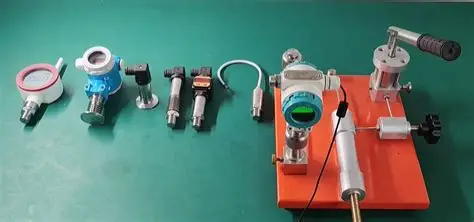
A piezoresistive pressure sensor measures pressure by turning the strain on a thin diaphragm into a change in electrical resistance. Diffused resistors form a Wheatstone bridge on a silicon chip. When pressure bends the diaphragm, the resistors stretch, their resistance shifts, and the bridge outputs a small voltage proportional to the applied pressure.
Because that output is a direct-current (DC) signal, a piezoresistive sensor can read a pressure that never changes, which is the property that separates it from a piezoelectric sensor and makes it the default choice for steady process measurement.
What a piezoresistive pressure sensor is
A piezoresistive pressure sensor is a device that converts applied pressure into an electrical signal using the piezoresistive effect: the change in a material’s electrical resistance when it is mechanically strained. In a pressure sensor, that strained material is a set of resistors diffused or implanted into a single-crystal silicon diaphragm.
The reading is proportional and continuous. If the diaphragm sees 50% of its rated pressure, the bridge produces roughly 50% of its rated output, and it holds that output for as long as the pressure is applied.
Silicon is used because its resistance changes far more per unit of strain than a metal foil gauge does, which gives the sensor a strong, clean signal from a very small deflection. That silicon behaves this way was first characterised by C. S. Smith in a 1954 study published by the American Physical Society, and it is the reason precision pressure sensing moved off metal foil and onto silicon.
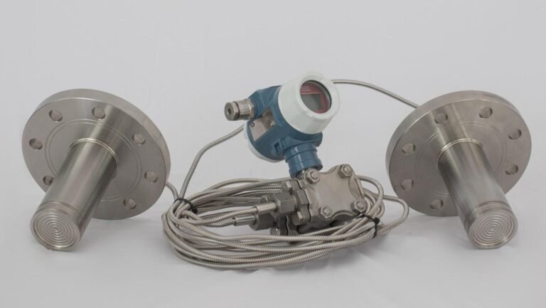
Two forms dominate industrial use. A diffused silicon element uses an oil-filled isolation diaphragm so the silicon chip never touches the process. A MEMS element etches the diaphragm and the bridge from the silicon wafer itself, which allows very small, very fast sensors. Both are piezoresistive; they differ in construction, not in principle.
The piezoresistive effect: strain becomes a signal
The signal chain is short, and nearly every specification you will later compare traces back to one of these four steps.
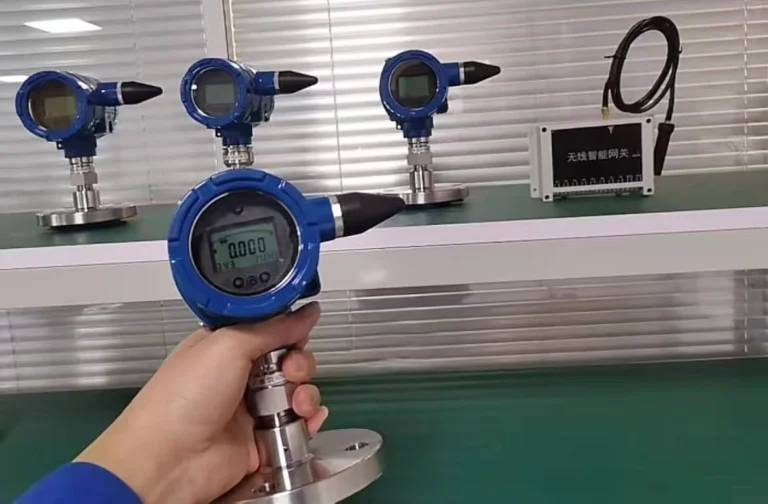
- Pressure deflects a diaphragm. Process pressure pushes on a stainless-steel diaphragm. In a diffused-silicon transmitter the pressure passes through a fill fluid to the silicon; in a MEMS sensor it acts on the etched silicon diaphragm directly.
- Strain changes resistance. Four resistors sit in a Wheatstone bridge on the diaphragm. Two stretch and two compress, so the bridge goes out of balance in proportion to the strain.
- The bridge outputs millivolts. With a constant excitation current or voltage, the imbalance appears as a differential millivolt signal. A bare element (for example a compact OEM sensor) may output that raw millivolt signal directly.
- Conditioning turns it into a standard output. A transmitter amplifies and temperature-compensates the bridge and re-scales it to 4-20 mA, 0-5 V, 0.5-4.5 V ratiometric, or a digital bus.
Temperature is the effect’s main source of error, because silicon resistance is itself temperature-sensitive. This is why quality piezoresistive transmitters are laser-trimmed and specify a compensated temperature range (typically around -10 to +60 °C) that is narrower than the operating range. For how that compensation is built and verified, see the pressure sensor temperature compensation guide. For the broader signal path from element to loop, see the pressure transmitter working principle.
Piezoresistive vs piezoelectric vs capacitive
The first selection decision is which sensing technology fits the measurement. The dividing question is simple: does the pressure hold still, or does it move fast?
| Property | Piezoresistive | Piezoelectric | Capacitive |
|---|---|---|---|
| Signal type | DC, continuous | AC, decaying | DC, continuous |
| Measures static pressure? | Yes | No (signal leaks to zero) | Yes |
| Best at | Static to high-frequency dynamic | Fast dynamic / shock only | High accuracy, low pressure, clean media |
| Absolute amplitude over seconds | Yes | No | Yes |
| Typical accuracy | ±0.1% to ±0.5% FS | Dynamic only | to ±0.075% FS |
| Fill fluid | Usually (diffused silicon) | No | No |
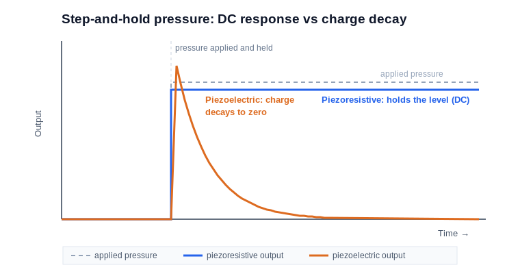
The piezoresistive vs piezoelectric line is about DC response. A piezoelectric crystal produces charge only while the pressure is changing, and that charge then bleeds away through the amplifier’s time constant. So a piezoelectric sensor generally cannot hold a baseline through a long event, and cannot report an absolute pressure that has been steady for several seconds.
In practice, if you need to read a pressure that is holding still, a piezoelectric sensor will drift back toward zero and mislead you. A piezoresistive sensor has true DC response, so it reports the actual pressure whether that pressure is static or moving.
This is why a piezoresistive element can serve both a slow process loop and a microsecond blast front, while piezoelectric is limited to fast dynamic and shock work. It is also why, for detonation and blast pressure, both Chinese and US military test standards name piezoresistive as the first-choice technology: it captures the rising edge and holds the long tail.
Capacitive sensing also gives a DC signal, and a ceramic capacitive cell can reach very high accuracy (down to ±0.075% FS) on clean media with no fill fluid. The full piezoresistive-versus-capacitive trade-off, including overload and media handling, is covered in a dedicated comparison: piezoresistive vs capacitive pressure sensors.
One silicon principle, static to dynamic
Because the piezoresistive effect works from DC upward, one sensing principle covers a range no single competing technology spans, across two families built on the same silicon idea.
The static family measures process pressures that change slowly relative to the sensor, which describes most of the pressure points you will meet in a plant: the general-purpose transmitters on a pump, a hydraulic line, a compressor or a tank. Response time is typically in the low milliseconds, which is generally ample for a control loop, so the design priority instead falls on accuracy, long-term stability and temperature compensation.
The dynamic family measures events rather than states, such as water hammer, combustion cycles, valve transients and blast waves, so here the design priority flips to speed. A dynamic piezoresistive sensor usually uses a cavity-less flush diaphragm, so no trapped gas column can resonate and distort the wavefront. Its natural frequencies typically reach into the megahertz, and its rise times fall below one microsecond.
It still outputs a DC-stable signal, so it captures the absolute amplitude of the event and not just its edges. That is the property that lets one silicon technology serve a use case a piezoelectric sensor cannot.
The same silicon-strain principle therefore reaches from a vacuum process transmitter to a free-field detonation probe. That continuity is the practical argument for piezoresistive: you can standardise one sensing technology across static and dynamic measurements instead of running two incompatible technologies.
How to select a piezoresistive sensor
Once you have settled on piezoresistive as the technology, five parameters size the actual sensor. Work through them in order.
- Range. Pick a full-scale near the top of your working pressure, so the reading uses most of the span. A sensor run constantly near zero wastes resolution.
- Overpressure and burst. Check the proof (overload) rating against the worst spike, not the working pressure. Pulsating lines and water hammer routinely exceed the working value; a common industrial rating is 2x full-scale proof, with burst several times higher.
- Media compatibility. The wetted diaphragm must survive the fluid. 316L stainless steel suits most water, oil, air and mild chemicals. Aggressive or crystallising media call for a flush diaphragm or a diaphragm seal.
- Temperature. Separate the operating range from the compensated range. Accuracy is guaranteed only inside the compensated band. Media hotter than the sensor’s operating ceiling need a siphon, a cooling element, or a high-temperature dynamic model.
- Bandwidth (dynamic only). Match bandwidth to the fastest event you must capture, and no more. As a working reference, roughly 0-20 kHz corresponds to a rise time near 16 µs, 0-100 kHz near 4 µs, and 0-200 kHz near 2 µs. Specifying more bandwidth than the event needs only admits more noise.
A worked example: say you must log the discharge pressure of a 24 V DC pump station over long cable to a PLC. You want a static transmitter, a full-scale a little above line pressure, 316L wetted parts, a 4-20 mA loop for noise immunity over distance, and an operating range that covers your coldest start. Accuracy of ±0.25% FS is typical for this duty.
One check applies across all five steps: the accuracy and temperature figures you compare are only trustworthy if they were measured to a published method. For industrial process transmitters that method is usually IEC 60770-1:2010, and in China GB/T 28474.1-2012, so a datasheet that cites neither is quoting a number you cannot check.
The calibration chain behind those numbers ultimately traces back through a national metrology institute such as NIST. How the temperature part of that error budget is built and verified is covered in the pressure sensor temperature compensation guide.
The HMK TECH piezoresistive range
HMK TECH builds the full piezoresistive spectrum on the same silicon-strain foundation, which is what lets one supplier cover both the static loop and the dynamic event. Specifications below are from the current product pages.
| Need | Model | Real specification (verified) |
|---|---|---|
| Best-selling general process | HM20 General Purpose | Piezoresistive diffused silicon; -100 kPa / 5 kPa to 100 MPa; ±0.25% FS; ≤2 ms; -40 to +85 °C; 4-20 mA / 0-5 V / 0.5-4.5 V; Ex ia optional |
| Compact OEM, raw output | HM10 Compact | Piezoresistive; raw mV output; ±0.1% FS; miniature OEM package |
| European OEM, 5 outputs | HE10 Diffused Silicon | Diffused silicon piezoresistive; 20 kPa to 600 bar; ±0.5% FS; -20 to +85 °C; 4-20 mA / 0-5 V / 1-5 V / 0.5-4.5 V / I2C; 500 g shock; IP67 |
| Ultra-miniature, high bandwidth | HM91 Micro | Ø2.54 mm piezoresistive; 1.6 MHz bandwidth |
| Dynamic / shock / blast | CYG400 series | MEMS piezoresistive; 20 kPa to 100 MPa; natural frequency 150 kHz to 1 MHz; rise time 0.2 to 5 µs; cavity-less flush diaphragm; DC-stable |
| High-temperature dynamic | CYG402 / CYG409 | CYG402 continuous 180 °C; CYG409 water-cooled to 450 °C, transient 2000 °C / 1000 ms |
| Free-field / underwater blast | CYG410-412 / CYG1413 / CYG1414 | Free-field probes; CYG1413 underwater IP68, 0-5 V; CYG1414 composite pressure + ground-stress |
For clean-media precision where a fill fluid is undesirable, HMK also offers ceramic capacitive (for example the HM12 at ±0.075% FS), which is the capacitive alternative discussed above rather than a piezoresistive part. To match a model to your pressure range and output, start from the pressure sensors and transmitters category or the OEM pressure transducer selection guide.
Frequently asked questions
Is a piezoresistive sensor good for static pressure?
Yes. Its output is a DC signal proportional to pressure, so it reads and holds a steady pressure indefinitely. This is the main reason it is used for process transmitters, where the pressure may not change for hours.
What is the difference between piezoresistive and piezoelectric?
A piezoresistive sensor changes resistance under strain and outputs a DC signal, so it measures both static and dynamic pressure. A piezoelectric sensor generates charge only while pressure changes, and that charge decays, so it measures dynamic and shock pressure only. For a pressure that must be held or read absolutely over seconds, piezoresistive is required.
What is the piezoresistive effect?
It is the change in a material’s electrical resistance when it is mechanically strained. Silicon shows a large piezoresistive effect, which is why silicon diaphragms with diffused resistor bridges make sensitive, stable pressure sensors.
Does a piezoresistive pressure sensor need a fill fluid?
Diffused-silicon types usually use an oil fill to isolate the silicon from the process. MEMS types can expose the etched silicon diaphragm directly. The fill fluid sets part of the temperature and media behaviour, so it matters in selection.
How accurate are piezoresistive pressure sensors?
Industrial piezoresistive transmitters typically range from about ±0.5% FS for economical OEM units to ±0.1% FS for high-accuracy models. Accuracy is specified inside the compensated temperature range; outside it, add the temperature coefficient.
Can one piezoresistive sensor measure both slow and fast pressure?
The principle spans both, but a single model does not. Static transmitters are optimised for stability at low-millisecond response; dynamic models are optimised for microsecond rise time and megahertz bandwidth. Choose the family that matches your event.