CYG400 Series — Piezoresistive Dynamic Pressure Sensor
Piezoresistive Dynamic Pressure Sensor: CYG400 Series Guide
Ten MEMS piezoresistive models for blast, shock, and high-frequency dynamic pressure measurement. Ranges from 20 kPa to 100 MPa, natural frequencies from 150 kHz to 1 MHz, rise times from 5 µs down to 0.2 µs. Cavity-less flush diaphragm. Anti-IR optical protection. Built to military-spec for detonation dynamic measurement.
What a Piezoresistive Dynamic Pressure Sensor Is
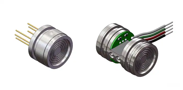
A piezoresistive dynamic pressure sensor uses a silicon-MEMS strain bridge bonded to a thin diaphragm. When pressure deforms the diaphragm, the bridge resistors change resistance, and an excitation circuit reads out the imbalance as a millivolt signal. “Dynamic” means the sensor is fast: rise times under one microsecond, natural frequencies into the megahertz range, capable of capturing blast wavefronts, water-hammer transients, and combustion-cycle pressures.
The CYG400 family is the piezoresistive dynamic line in the HMK pressure portfolio. Ten models cover everything from a 20 kPa air-shock measurement to a 100 MPa hydraulic transient, and they share three signature traits: a cavity-less fully-flush diaphragm (no acoustic resonance to corrupt the wavefront), an anti-IR optical coating (so a near-field detonation flash cannot saturate the silicon), and DC-stable output (the signal stays true from rising edge through long tail).
Two distinctions worth keeping in mind. First, this is not a static pressure transmitter; the static line, like our general-purpose pressure transmitters, is built for slow process loops, not for shock events. Second, this is not a piezoelectric sensor; piezoelectric output decays through a charge time constant, so it cannot hold a baseline through a long event or capture absolute amplitude over seconds. Both Chinese and US military standards recommend piezoresistive sensors as the first choice for detonation dynamic measurement.
CYG400 Series Common Specifications
All ten CYG400 models share the same MEMS piezoresistive sensing core, stainless flush diaphragm, and anti-IR optical option. The table below covers what is common across the family; the next section breaks out per-model range, frequency, and rise-time differences.
| Group | Parameter | Value |
|---|---|---|
| Sensing | Technology | MEMS piezoresistive silicon strain bridge |
| Diaphragm | Stainless steel, fully flush, cavity-less | |
| Anti-light interference | Anti-IR optical coating (option F4) | |
| Range & Speed | Range span (series) | 20 kPa … 100 MPa across the ten models |
| Natural frequency | 150 kHz … 1 MHz, model-dependent | |
| Rise time | 0.2 … 5 µs, model-dependent | |
| Accuracy | Sensor accuracy | 0.25% / 0.5% FS |
| Transmitter accuracy | 0.5% / 1.0% FS (CYG1413/1414) | |
| Non-linearity | ±0.2% … ±1% FS | |
| Zero drift | 0.1 mV / 8 h | |
| Power & Output | Sensor power | 1 mA / 1.5 mA constant current, or 12 VDC constant voltage |
| Transmitter power | ±15 VDC, or 12–24 VDC | |
| Output | Differential mV (sensor) or 0–5 V amplified (transmitter) | |
| Environment | Operating temp (typical) | -40 to +85°C; up to +180°C (CYG402); +450°C (CYG409 water-cooled) |
| Transient peak temp | +2000°C / 100 ms (most models); +2000°C / 1000 ms (CYG409) | |
| Wetted material | Silicon + stainless steel; non-corrosive media (special media on request) |
Ten Models — One Master Comparison Table
The CYG400 family fans out into ten models grouped by mounting form: cased pressure-tap mount (CYG401, 402, 405, 406, 409), free-field probe (CYG410, 411, 412), underwater transmitter (CYG1413), and composite probe with simultaneous ground-stress channel (CYG1414). Use this table as your first selection step; the application matrix and mounting sections below show how the rows map onto specific use cases.
| Model | Range | Natural freq | Rise time | Mounting | Best for |
|---|---|---|---|---|---|
| CYG401 | 4–100 MPa | 180–1000 kHz | 0.2–0.5 µs | Cased, M20×1.5 | General mid-high pressure, hydraulic transient |
| CYG402 | 1–100 MPa | 180–1000 kHz | 0.2–1 µs | Cased, M20×1.5 | Continuous 180°C; combustion, exhaust |
| CYG405 | 300–800 kPa | 150–180 kHz | sub-µs | Cased, M20×1.5 | Liquid medium, low-pressure blast |
| CYG406 | 20–800 kPa | 5 to >300 kHz | 0.5–5 µs | Cased, M20×1.5 | Micro-pressure, wind shock, low-amplitude DP |
| CYG409 | 1 kPa–100 MPa | 200–1000 kHz | µs-level | Water-cooled jacket | Continuous 450°C; furnace, exhaust manifold |
| CYG410 | 300–800 kPa | 150–180 kHz | 1 µs | Free-field probe Φ6.5×406 mm | Outdoor low-pressure blast wavefront |
| CYG411 | 1–10 MPa | 180–360 kHz | 0.5–1 µs | Free-field probe Φ6×406 mm | Mid-pressure free-field detonation |
| CYG412 | 20–100 MPa | 450–1000 kHz | 0.2–0.3 µs | Free-field probe Φ8×405 mm | High-pressure near-field detonation |
| CYG1413 | 20–100 MPa | 450–1000 kHz | 0.2–0.3 µs | Underwater transmitter | Underwater explosion shock-wave |
| CYG1414 | 2–100 MPa total + 0.3–100 MPa ground stress | 240–1000 kHz | 0.2–1 µs | Composite probe | Free-field detonation + ground stress |
A quick decision rule: free-field probes for outdoor blast, cased models for engine-room and hydraulic, water-cooled for furnace temperatures, and the 1413 / 1414 transmitters for the two specialty contexts — underwater explosion and combined pressure-plus-ground-stress.
Where Each CYG400 Model Fits
Roughly 90% of CYG400 shipments fall into one of six application contexts. Match the use case to the model below; spec details are in the comparison table above.
Military & Ballistic Testing
Free-field detonation pressure, projectile ballistics, energetic-materials characterization. Use CYG410 / 411 / 412 free-field probes for outdoor blast; CYG412 for high-pressure near-field where IR-flash protection matters.
Hydraulic-Power R&D
Pressure ripple, water hammer, valve-actuation transients on hydraulic test rigs. CYG401 covers the 4–100 MPa hydraulic working range with sub-microsecond rise time.
High-Temperature Combustion
Engine cylinders, exhaust manifolds, furnace pressure. CYG402 to 180°C continuous; CYG409 water-cooled to 450°C and 2000°C / 1000 ms transient.
Materials & Civil Shock Loading
Hopkinson bar, drop-weight rigs, soil-shock and structure-blast research. CYG401 / 402 cased for instrumented bars; CYG410 / 411 free-field for blast against structures.
Traumatic-Medicine Research
Blast-injury studies, ballistic-gel pressure measurement, shock-tube experiments. CYG406 covers the kPa-range pressures that gel and tissue surrogates produce.
Underwater & Composite Free-Field
Underwater explosion shock-wave (CYG1413, IP68 transmitter, 0–5 V output) and combined free-field pressure + ground-stress measurement (CYG1414 composite probe).
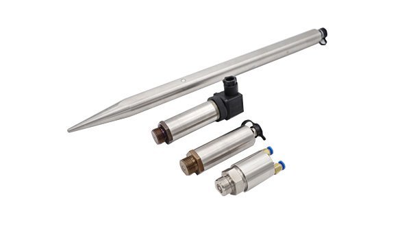
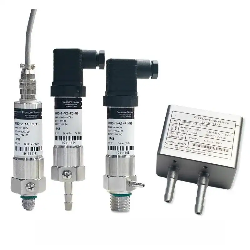
Mounting Forms: Cased, Free-Field, Underwater, Composite
The CYG400 family ships in four physical forms. Pick the form first; the per-model spec table narrows the rest.
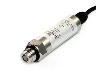
Cased (CYG401, 402, 405, 406, 409). M20×1.5 thread, ED-seal ring, dial-on-cap form factor; housing diameter ~Φ27 mm. Mounts into a dedicated pressure tap on an engine, manifold, hydraulic line, or test fixture. Wiring exits the cap as a shielded cable. The housed group is the workhorse for engine-room, hydraulic, and instrumented-bar work.
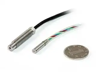
Free-field probe (CYG410, 411, 412). Streamlined teardrop, Φ6 to Φ6.5 mm diameter, 406 mm probe length. Designed for low-distortion wavefront capture: the slender form means the sensor barely perturbs the incoming wave, so what you measure is what is there. Used outdoors in detonation arenas, attached to a ground stake or a wave-aligned mount.
Water-cooled (CYG409). Cased body inside a water-cooling jacket. Cooling water inlet pressure must be at least 300 kPa (700 kPa for explosion-proof installations); pump flow ~2 L/min. Continuous service to 450°C; transient to 2000°C for 1000 ms. Used on furnace pressure taps, exhaust manifolds, and any continuous-high-temperature pressure measurement.
Underwater transmitter (CYG1413). Waterproof housing 195 mm × 132 mm, fully sealed waterproof cable, internal amplifier delivering 0–5 V output so cable runs do not need a separate charge amplifier topside. Operating temperature 0–50°C in water. Used in submerged blast-test pools, ship-shock trials, and oceanographic shock measurement.
Composite probe (CYG1414). Single integrated probe carrying both a free-field pressure sensing element and a ground-stress sensing element, so one cable returns two synchronized channels. Used when soil shock and free-field pressure must be correlated at the same point.
CYG400 Selection & Ordering Code
For the CYG14XX transmitter line (CYG1413, CYG1414) the order code follows this format:
CYG <model> <range> <accuracy> <power+output> <cable> <mount> <anti-IR> <custom>
| Segment | Code | Meaning |
|---|---|---|
| Accuracy | P3 / P4 / P5 | 0.25% / 0.5% / 1.0% FS |
| Power + Output | S4 | mV out / 1 mA, 1.5 mA constant current |
| S7 | mV out / 12 VDC constant voltage | |
| S11 | 0–5 V / 12–24 VDC / 120 kHz BW | |
| S12 | 0–5 V / ±15 VDC / 20 kHz BW | |
| S13 / S14 | 0–5 V / 100 kHz BW (S13) or 200 kHz BW (S14) | |
| Cable | C1 | Direct lead |
| C2 | Aviation connector | |
| C3 | Round connector | |
| C4 | IP68 waterproof connector | |
| Mount | A1 / A6 | M20×1.5 / user-defined thread |
| Anti-IR | F4 | Anti-IR optical coating (recommended for near-field detonation) |
| Custom | Q | Custom selection sheet (special temp, special media, etc.) |
Worked example: CYG 1413 (0–100 MPa) P5 S12 C4 A1 F4 Q — underwater transmitter, 100 MPa range, 1.0% accuracy, 0–5 V output with 20 kHz bandwidth on ±15 VDC, IP68 waterproof connector, M20×1.5 thread, anti-IR optical, custom sheet attached.
Bandwidth-rise time relation (PDF page 12 reference): 0–20 kHz BW → rise time ≥ 16 µs; 0–100 kHz BW → rise time ≥ 4 µs; 0–200 kHz BW → rise time ≥ 2 µs. Pick the bandwidth that matches the fastest event you need to capture — specifying more bandwidth than the event needs only widens noise.
CYG400 Series FAQ
Technical Support
Three background guides for engineers specifying or commissioning a CYG400 dynamic pressure sensor. Open in a new tab; the deep-dives complement the spec-and-selection focus of this page.
Ready to Specify a CYG400?
Send us the pressure event — expected peak amplitude, the rise time you need to capture, the mounting context (cased pressure tap, free-field outdoors, underwater, or composite probe), and the temperature environment. Our pressure-instrument engineers will reply with a CYG400 model, ordering code, and lead time.
Our engineers typically respond within 12 business hours with detailed technical specifications.