CYG401 — High-Frequency Dynamic Pressure Sensor
CYG401 High-Frequency Dynamic Pressure Sensor: 4 to 100 MPa Series
Baseline MPa-range piezoresistive dynamic pressure sensor of the CYG400 family. Cavity-less flush diaphragm, dual-bridge compensation, 4 to 100 MPa across 7 ranges, 180 to 1000 kHz natural frequency, sub-microsecond rise time. Designed for explosion shock-wave, hydraulic-machinery, and materials-science dynamic measurement. Anti-IR optical interference protection optional.
What a High-Frequency Pressure Sensor Is
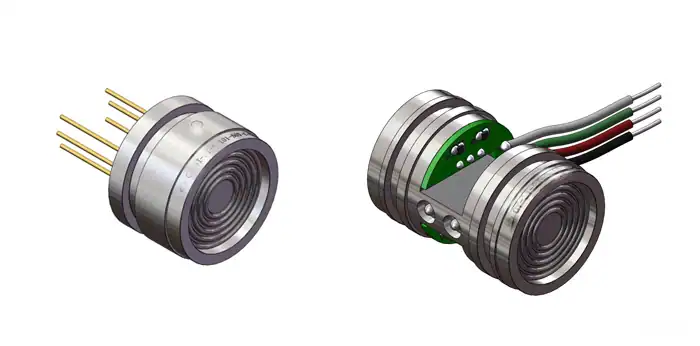
A dynamic pressure sensor captures the rising edge and waveform of a transient pressure event — a detonation shock, a hydraulic pulse, a piston end-of-stroke spike — with bandwidth fast enough to resolve features in the microsecond range. The CYG401 sits at the baseline of HMK’s dynamic CYG400 family, and the dual-bridge piezoresistive element gives a true DC reference through the entire transient, unlike a piezoelectric crystal which loses static reference as charge bleeds off.
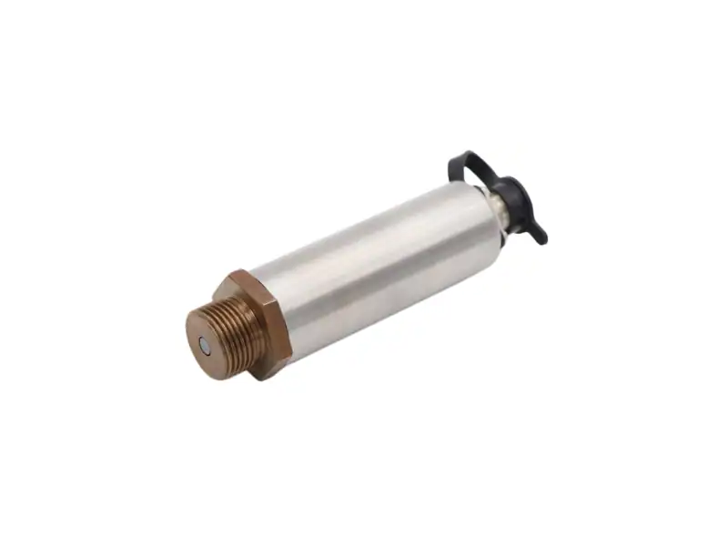
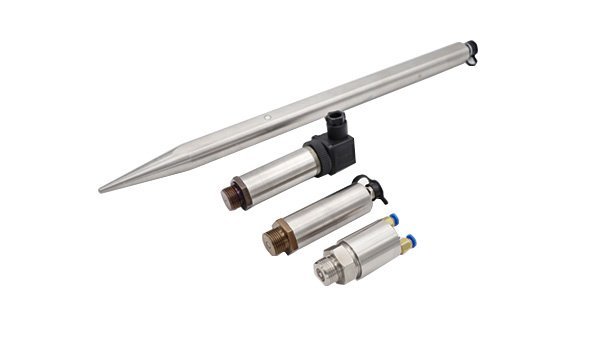
The CYG401 is the baseline MPa-range variant of the CYG400 piezoresistive dynamic pressure family. The sensor housing is cylindrical with the stainless-steel diaphragm flush at the wetted face. Two design choices keep distortion low: the dual-bridge piezoresistive sensing element compensates zero drift and temperature effects in real time, and the diaphragm sits flush with the sensor surface in a cavity-less mount, so there is no internal acoustic resonance to corrupt the rising edge.
Seven ranges from 4 MPa to 100 MPa cover the heart of dynamic shock-wave measurement — the regime where chemical-detonation pressure profiles, hydraulic-pulse spikes, and materials-science high-rate loading studies live. For sustained or transient temperature above 85°C, switch to the CYG402 high-temperature dynamic; for liquid-medium or below-MPa pressures, the CYG405.
CYG401 Technical Specifications
| Group | Parameter | Value |
|---|---|---|
| Sensing | Technology | MEMS piezoresistive silicon strain bridge |
| Diaphragm | Stainless steel, fully flush, cavity-less | |
| Anti-light interference | Anti-IR optical coating (option F4) | |
| Range & Speed | Range span | 4 / 6 / 10 / 20 / 40 / 60 / 100 MPa |
| Natural frequency | 180 kHz (4 MPa) to 1000 kHz (100 MPa), range-matched | |
| Rise time | 0.5 µs (4–10 MPa) to 0.2 µs (60–100 MPa) | |
| Accuracy | Sensor accuracy | 0.25% / 0.5% FS |
| Non-linearity | ±0.2% … ±1% FS | |
| Zero drift | 0.1 mV / 8 h | |
| Power & Output | Power | 1 mA / 1.5 mA constant current, or 12 VDC constant voltage |
| Output | Differential mV signal | |
| Mechanical | Form factor | Cylindrical stainless-steel housing, flush diaphragm, M20×1.5 mount thread |
| Mounting thread | M20×1.5 | |
| Wetted material | Silicon + stainless steel; non-corrosive media | |
| Environment | Operating temp | -40 to +85°C standard; -55 to +125°C extended |
| Transient peak temp | +2000°C / 100 ms (with optional protective measures) |
Range Selection: Seven Models, One Housing Form
The CYG401 ships with seven pre-defined ranges. The housing, mounting thread, and dual-bridge piezoresistive sensing element are identical across all seven — only the diaphragm thickness and natural frequency are range-matched. Pick the range whose full-scale value sits ~30-50% above the expected peak amplitude of your event, so you keep both headroom and bridge sensitivity.
| Range | Natural frequency | Rise time | Typical event |
|---|---|---|---|
| 0–4 MPa | 180 kHz | 0.5 µs | Low-MPa hydraulic pulse, gas-deflagration vessel tests |
| 0–6 MPa | 250 kHz | 0.5 µs | Hydraulic pulse, valve transients, low-energy detonation |
| 0–10 MPa | 320 kHz | 0.5 µs | Internal ballistics, propellant burn-rate characterization |
| 0–20 MPa | 450 kHz | 0.3 µs | Mid-energy detonation, gel impact |
| 0–40 MPa | 600 kHz | 0.3 µs | Higher-energy LP detonation; faster response |
| 0–60 MPa | 800 kHz | 0.2 µs | High-energy detonation, internal ballistics late-stage |
| 0–100 MPa | 1000 kHz | 0.2 µs | Top of CYG401 band; high-energy near-field detonation, hypervelocity impact |
The 60 MPa and 100 MPa top ranges run at 800 and 1000 kHz natural frequency with 0.2 µs rise time, so the rising edge captures the fastest detonation transients in the family. If your event runs above 85°C operating or transient temperature above 125°C, step up to CYG402; for sub-MPa liquid-medium work, use CYG405.
Where the CYG401 Is Used
The 4-100 MPa dynamic band covers the bulk of mid-to-high-energy dynamic events — chemical detonations in confined chambers, hydraulic pulse-pressure work, internal-ballistics dynamic measurement, and materials-science Hopkinson-bar style work where the peak sits well into the MPa region and rise time stays in the sub-microsecond regime.
Confined-Chamber Detonation
Detonation pressure profiles in confined test chambers, internal ballistics dynamic measurement, propellant burn-rate characterization where peak amplitude lands between 4 and 100 MPa.
Hydraulic Pulse Testing
Hydraulic pulse-pressure testing on pumps, valves, cylinders, and accumulators. Captures pressure spikes at piston end-of-stroke, valve transients, and water-hammer in piping.
Materials-Science Dynamic Loading
Materials-science dynamic loading: split-Hopkinson pressure bar (SHPB), gas-gun impact testing, projectile-impact instrumentation in materials characterization labs.
Shock-Tube Research
Shock-tube and impulse-pipe instrumentation operating in the MPa range — diaphragm-rupture profiles, gas-dynamic transients, propagating wavefronts in confined geometries.
Ballistic-Gel & Medical
Traumatic-medicine and biomechanics research: blast-injury work on ballistic gelatin and tissue surrogate where transmitted pressure into the MPa range needs sub-microsecond resolution to match real-event kinetics.
Energetic-Materials Screening
Civil-engineering and structural-dynamics work: rock-blasting characterization, controlled-demolition instrumentation, dynamic-loading studies on test fixtures and load cells in MPa range.
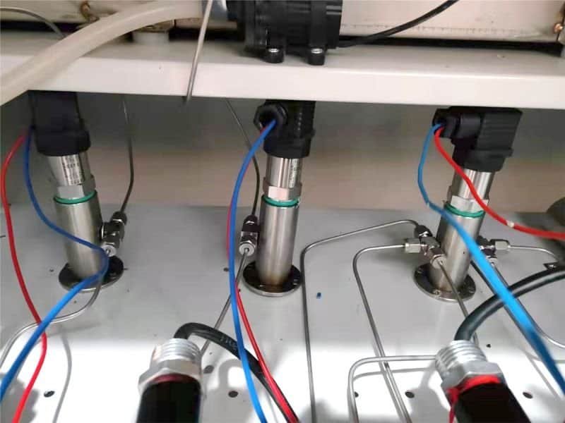
Installation: Probe Orientation and Mounting
A dynamic sensor gives a clean reading only when mounted and powered correctly. Three rules cover most CYG401 installations across the MPa-range family.
Diaphragm face orientation. Mount the sensor so its flush diaphragm sits at the wetted face of the pressure chamber or pipe wall, parallel to the wavefront. The cavity-less mount avoids any volume between the wave and the silicon bridge that would add Helmholtz resonance to the rising edge. Off-axis or recessed installation of more than ~15° introduces angle-dependent error in peak amplitude.
Mount support. Clamp on the M14×1.5 mounting thread. Mount the sensor flush with the test-chamber wall or port adapter so the diaphragm sits at the wetted surface. Do not clamp on the sensor body — clamping on the body adds bending mode to the sensor and corrupts the rising edge with mechanical resonance. Keep the cable run away from the line-of-sight to the source.
Standoff distance. Place the sensor at the radial distance you want to characterize. For repeatability, fix the probe-to-source distance precisely and record it with the test — pressure scales steeply with distance in the near-to-mid field of a detonation, so a 10% distance error becomes a 20-30% pressure error. Mount the CYG401 on a port adapter or wall fitting that holds the diaphragm flush with the pressure boundary; do not let the sensor body sit in a recessed cavity or behind a step that adds an acoustic volume in front of the diaphragm.
CYG401 Ordering Code
Standard order format:
CYG401 <range> <accuracy> <cable> <anti-IR> <custom>
| Segment | Code | Meaning |
|---|---|---|
| Range | 4 / 6 / 10 / 20 / 40 / 60 / 100 | Full-scale value in MPa, 7 ranges |
| Accuracy | P3 / P4 | 0.25% / 0.5% FS |
| Cable | C1 | Direct lead, standard length |
| CS | Double-shielded twisted anti-interference cable (recommended ) | |
| Anti-IR | F4 | Anti-IR optical coating (recommended for near-field detonation) |
| Custom | Q | Custom cable length, special temperature, or custom thread |
Worked example: CYG401 6 P3 CS F4 Q — 0–6 MPa range, 0.25% accuracy, double-shielded cable, anti-IR optical coating, custom 25 m cable length per attached sheet.
CYG401 FAQ
Technical Support
Three background guides for engineers specifying or commissioning the CYG401 high-frequency dynamic sensor. Open in a new tab; the deep-dives complement the spec-and-selection focus of this page.
Ready to Specify a CYG401?
Send us the expected peak amplitude (MPa), the operating temperature, whether IR flash from the event is in play, and the cable run length and EMI environment. Our pressure-instrument engineers will reply with a CYG401 range-and-options recommendation within 12 business hours. Or pick from the CYG401 range, ordering code, and lead time.
Our engineers typically respond within 12 business hours with detailed technical specifications.