CYG400 Series · Cased Low-Pressure
CYG405 Low-Pressure Dynamic Pressure Sensor
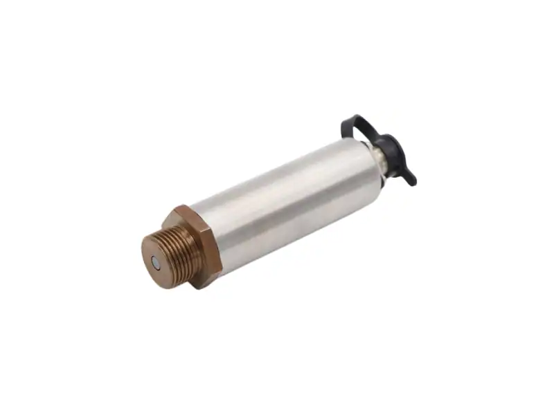
A piezoresistive sensor purpose-built for the 300–800 kPa low-pressure dynamic regime where most blast and water-medium events live. Cavity-less flush diaphragm prevents the curl that wrecks low-amplitude readings; sub-microsecond rise time captures the wavefront; optional anti-IR coating keeps a flash bulb from saturating the silicon.
300–800
kPa Range
150–180
kHz Natural Freq
<1 µs
Rise Time
0.25%
FS Accuracy
Overview · Specifications · Features · Applications · Dimensions · Ordering Guide · Related · FAQ · Contact
Overview
The CYG405 sits inside the CYG400 series at the low-pressure cased-mount slot. Six configurable spans cover 300, 400, 500, 600, 700, and 800 kPa — a band that catches most water-medium blast events, hydraulic water-hammer transients, and ballistic-gel pressure footprints that the higher-range CYG401 / 402 cannot resolve without truncating the signal.
The MEMS piezoresistive strain bridge is bonded to a cavity-less flush diaphragm. The flush face matters in low-pressure dynamic work: a recessed sensing element invites diaphragm curl at the leading edge of a wavefront, which shifts the apparent rise time by tens of microseconds and rounds peaks that a piezoelectric sensor would clip. The cavity-less design holds the diaphragm flat through the event and reads true amplitude through the long tail — the kind of DC-stable response that piezoelectric charge-mode sensors cannot deliver because their charge decays through the time constant.
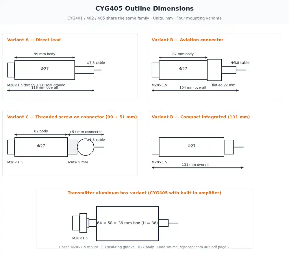
Two configuration flags are worth knowing about up front. First, the F4 anti-IR optical coating: standard recommendation for any near-field detonation with a visible flash, because silicon is photoresponsive and an unshielded sensor near a flash event can saturate. Second, the cased M20×1.5 mount: ED seal-ring groove built in, Φ27 body, four wiring-out form factors (direct lead, aviation connector, screw-on connector, integrated transmitter box) all sharing the same mounting interface as the CYG401 / 402 sister models. See the dimensions section for the four mechanical variants and the ordering guide for the order-code segments.
Specifications
Range & speed (per range-band, from manufacturer datasheet)
| Pressure range (kPa) | 300 | 400 | 500 | 600 | 700 | 800 |
|---|---|---|---|---|---|---|
| Natural frequency (kHz) | 150 | 150 | 150 | 180 | 180 | 180 |
| Rise time | sub-microsecond (< 1 µs) across all ranges | |||||
Common specifications (all CYG405 ranges)
| Parameter | Value |
|---|---|
| Sensing technology | MEMS piezoresistive silicon strain bridge |
| Diaphragm | Stainless steel, fully flush, cavity-less |
| Sensor accuracy | P3: 0.25% FS · P4: 0.5% FS · P5: 1.0% FS (selectable) |
| Sensitivity tolerance | 0.5% / 1.0% |
| Non-linearity | ±0.2% to ±0.5% FS |
| Zero drift | 0.2 mV / 8 h (P3) · 0.5 mV / 8 h (P4 / P5) |
| Zero temperature coefficient | 0.03% FS / °C |
| Sensitivity temperature coefficient | 0.03% FS / °C (P3) · 0.05% FS / °C (P4 / P5) |
| Operating temperature | -40 to +85 °C standard (-55 to +125 °C special order) |
| Compensated temperature | 0 to +70 °C (custom available on request) |
| Sensor power | 1 mA / 1.5 mA constant current, or 12 VDC constant voltage |
| Transmitter power | ±15 VDC, or 12–24 VDC |
| Output | Differential mV (sensor) · 0–5 V or dual-excitation +5 V (with transmitter) |
| Anti-light interference | Anti-IR optical coating, optional (order code F4) |
| Wetted material | Silicon + stainless steel; non-corrosive media (special coating on request) |
| Mounting | Cased M20×1.5 thread with ED seal-ring groove · Φ27 body |
Key Features
Low-Pressure Sweet Spot
Six configurable spans across 300–800 kPa target the dynamic regime where most blast and water-medium events live. A higher-range sensor at this amplitude either truncates the leading edge or loses resolution; CYG405 keeps the full waveform.
Cavity-Less Flush Diaphragm
The sensing element sits flush with the process face. No recess means no diaphragm curl at the wavefront, no ringdown artefact, and no amplitude drop at low ΔP. Critical when the event you are measuring is itself only a few hundred kPa.
DC-Stable Piezoresistive Output
Unlike piezoelectric (charge-mode) sensors, the silicon strain bridge holds a baseline indefinitely. The full rising edge, peak, and long tail are captured without charge-amplifier decay — true absolute amplitude through the event.
Sub-Microsecond Rise Time
150–180 kHz natural frequency, < 1 µs rise time. Bandwidth and rise time scale together: pick the order-code bandwidth (20 / 100 / 120 / 200 kHz) that matches the fastest event you need to capture. See the ordering guide.
Anti-IR Optical Coating (F4 option)
Silicon is photoresponsive — a near-field detonation with visible flash can saturate an unshielded sensor and lose the signal. The optional F4 anti-IR coating absorbs the flash so the bridge keeps reading pressure, not light.
Cased M20×1.5 with ED Seal Groove
Same mounting interface as the CYG401 / 402 sister models in the cased family. Four wiring-out form factors — direct lead, aviation connector, screw-on connector, integrated transmitter box — share the M20×1.5 thread plus ED seal-ring groove for repeatable, sealed installation.
Applications
Underwater Shock — Shallow Pool
Submerged blast-test pools and ship-shock trials produce wavefronts that water-attenuates to the 300–800 kPa band by the time they reach a sensor on a fixture wall. CYG405 catches the full waveform; the higher-range CYG401 would read mostly noise floor at the same amplitude.
Hydraulic Water-Hammer Capture
Valve-slam transients on hydraulic test rigs typically peak at 200–600 kPa above the steady-state working pressure. The dynamic component is what causes long-term pipe fatigue, and a static transmitter cannot see it. CYG405 reads the pulse train directly.
Ballistic Gel — Tissue Surrogate
Blast-injury research presses sensors into ballistic gel or tissue surrogates and reads the propagated pressure footprint. Surrogate compliance limits the wavefront to a few hundred kPa, which is exactly the CYG405 sweet spot.
Pipe Pulse Fatigue Rigs
Cyclic-pressure fatigue testing on pipework, accumulators, and pressure vessels imposes repeated 100–800 kPa pulses to characterise crack initiation. The cased M20×1.5 mount installs directly into a test-fixture sidewall.
Confined-Geometry Wavefront
Narrow vent ducts, blast galleries, and instrumented bunker tests confine the wavefront amplitude well below the open-air free-field equivalent. CYG405 covers the low-amplitude regime that the CYG410 free-field probe is too low-sensitivity to read.
Shock Tube — Driven Section Diagnostics
In a shock-tube driven section the steady-state operating pressure rides at 100–700 kPa absolute with millisecond-scale step changes; CYG405 captures the step edge with sub-microsecond rise and DC-stable amplitude across the dwell.
Dimensions
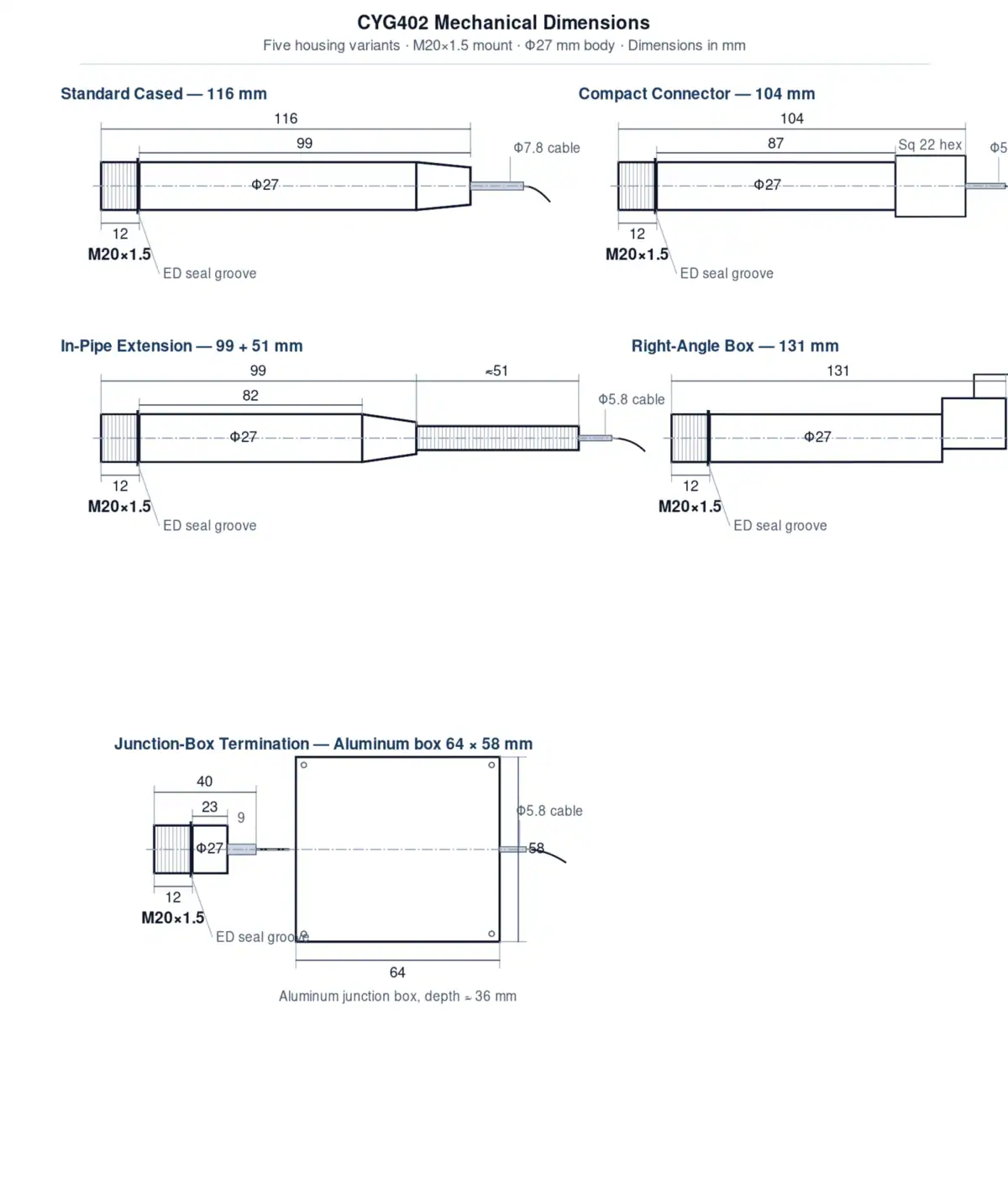
CYG401, CYG402, and CYG405 share the same family mounting interface: M20×1.5 thread, ED seal-ring groove, Φ27 body. The variant comes from how the wiring exits the cap. Pick the form factor that matches your fixture cable routing — the spec inside the cap is identical across all four.
Ordering Guide
The CYG405 order code follows the family format:
CYG405-<range>-P<accuracy>-S<power+output+BW>-C<cable>-A<mount>-F<antiIR>-Q<custom>| Segment | Code | Meaning |
|---|---|---|
| Range | 300 | 0–300 kPa |
| 400 | 0–400 kPa | |
| 500 | 0–500 kPa | |
| 600 | 0–600 kPa | |
| 700 | 0–700 kPa | |
| 800 | 0–800 kPa | |
| Accuracy | P3 | 0.25% FS |
| P4 | 0.5% FS | |
| P5 | 1.0% FS | |
| Power + Output + Bandwidth | S4 | mV output / 1 mA or 1.5 mA constant current |
| S7 | mV output / 12 VDC constant voltage | |
| S11 | 0–5 V / 12–24 VDC / 120 kHz BW | |
| S12 | 0–5 V / ±15 VDC / 20 kHz BW | |
| S13 | 0–5 V / ±15 VDC / 100 kHz BW | |
| S14 | 0–5 V / ±15 VDC / 200 kHz BW | |
| Cable | C1 | Direct lead |
| C2 | Aviation connector | |
| C3 | Round connector | |
| C4 | IP68 waterproof connector | |
| Mount | A1 | M20×1.5 (standard) |
| A6 | User-defined thread | |
| Anti-IR | F4 | Anti-IR optical coating (recommended for near-field detonation with visible flash) |
| Custom | Q | Custom selection sheet (special temperature, special media, etc.) |
Worked example. A 0–600 kPa CYG405 with 0.25% FS accuracy, 0–5 V output on ±15 VDC with 100 kHz bandwidth, aviation connector, M20×1.5 thread, anti-IR coating, no special customisation:
CYG405-600-P3-S13-C2-A1-F4Bandwidth — rise-time relation. Picking S12 (20 kHz BW) means rise time ≥ 16 µs; S11 / S13 (100–120 kHz BW) means rise time ≥ 4 µs; S14 (200 kHz BW) means rise time ≥ 2 µs. Match the bandwidth to the fastest event you need to capture — specifying tighter than required adds cost without adding usable signal.
Frequently Asked Questions
Need a Low-Pressure Dynamic Sensor for Liquid-Medium Blast?
Send us your event amplitude window, mounting form factor (cased / free-field / underwater), and required bandwidth. Our application engineers will recommend the right range band and order code, including whether the F4 anti-IR option is needed for your test environment.
Our engineers typically respond within 12 business hours with detailed technical specifications, lead time, and pricing.