Hydrostatic Level Measurement: Submersible vs DP, Explained by Physics
Hydrostatic Level Measurement in 30 Seconds
Hydrostatic level measurement reads how high a liquid sits in a tank by sensing the pressure that column of liquid creates at a fixed point. The physics is one equation:
For choosing and sizing a probe specifically for a borehole, see our guide to the well water level sensor.
P = ρ · g · h
A sensor sees pressure P. You already know fluid density ρ and gravitational acceleration g. What falls out is height h. The same physics carries two field implementations: a submersible probe dropped to the tank bottom, or a differential-pressure (DP) transmitter tapped on the side. Most submersible probes for water-like fluids span 0–10 mH₂O at around 0.25 % FS accuracy, with a 4–20 mA output that wires straight into the existing loop.
The deciding question is not whether hydrostatic works (it does, in most non-vacuum tanks) but which configuration matches your tank, fluid, and maintenance access. The next section explains the physics, then two hub-and-spoke sections route you to the configuration deep-dive you need.
The Physics: P = ρgh, Explained Once
A static column of liquid presses on whatever sits below it. Pressure at depth h equals fluid density ρ times gravity g times height. The result is independent of the tank’s cross-section, shape, or sidewall slope. A 10-meter water column in a slender pipe and a 10-meter water column in a 30-meter-wide reservoir generate the same bottom pressure.
For water at standard gravity (9.806 65 m/s², maintained by NIST Pressure Metrology in the U.S. and codified by ISO 80000-4), one meter of head equals roughly 9.806 kPa. Density scales the relationship linearly. The table below is the field shortcut:
| Fluid | Specific gravity (SG) | Pressure per meter of column |
|---|---|---|
| Fresh water (20 °C) | 1.000 | 9.81 kPa/m (1.42 psi/ft) |
| Light hydrocarbon (kerosene) | ~0.80 | 7.84 kPa/m |
| Diesel | ~0.85 | 8.34 kPa/m |
| Brine / heavy slurry | ~1.20 | 11.77 kPa/m |
| Sulfuric acid (98 %) | ~1.83 | 17.95 kPa/m |
Inverting for level gives h = (P_measured − P_atm) / (ρ · g). The P_atm term is why an “open” tank still needs an atmospheric reference; without it, every weather front would look like a level swing. A submersible probe handles this with a vented cable. A DP transmitter handles it by routing the low-pressure port to the tank’s top air space (or to atmosphere on an open tank).
Punch the numbers in our hydrostatic pressure calculator, which uses the same formula and lets you sweep SG. For the reverse direction — when you already have a pressure reading and need the depth — use the pressure to liquid level calculator. For the broader gauge-vs-absolute-vs-differential framing, see our gauge-pressure formula walk-through. For an open-textbook treatment of the physics underneath, see Control.com’s chapter on hydrostatic pressure for level.
One equation, two configurations. The next two sections show how each one implements it.
Submersible or DP: Two Paths From the Same Physics
The two industrial paths from P = ρgh look very different but answer the same physics.
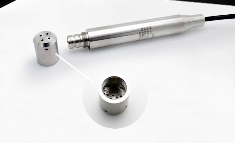
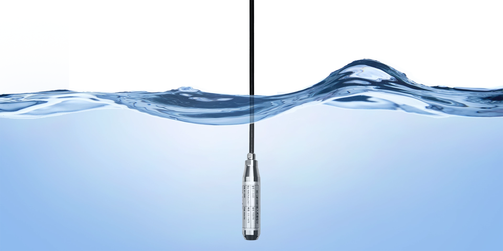
Submersible probe path. A small pressure transmitter, with diaphragm at the nose and electronics potted in a stainless or titanium body, is lowered to the tank bottom on a vented cable. The diaphragm sees ρgh. The vent inside the cable references atmosphere, so any barometric shift is automatically subtracted. This path fits open tanks, deep wells, lift stations, reservoirs, and chemical tanks where you can drop a cable in and pull it out for service. HMK ships four common variants:
- HM21 submersible level transmitter — 316L stainless, the workhorse for clean and brackish water
- HM21R anti-corrosive submersible — ceramic capacitive sensor with titanium body for sodium hypochlorite, dilute acids, seawater
- HM21F lightning-protected — gas-discharge plus TVS suppression for outdoor wells and unsheltered lift stations
- HM210 wireless level sensor — LoRa output for tanks far from existing 4–20 mA wiring
For the full variant-vs-failure-mode matrix and field-tech playbook, see Submersible Level Transmitter: 6 Failure Modes That Destroy Accuracy.
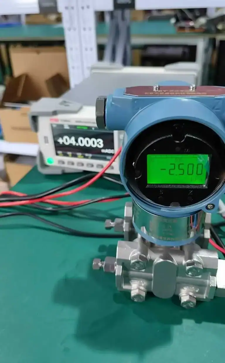
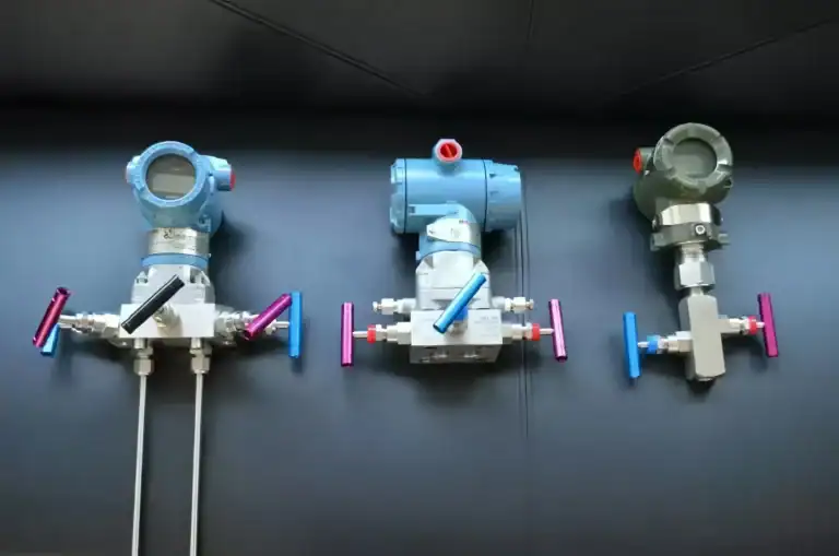
DP transmitter path. A differential-pressure transmitter taps the tank on the side (HP port at the bottom flange) and references the tank’s top air space or atmosphere on the LP port. The transmitter reads ΔP = ρgh directly. This path fits sealed and pressurized tanks where a submersible would be exposed to gas-blanket pressure shifts, and any service where the user wants no wetted parts inside the tank. HMK’s anchor here is the HM3051 smart differential pressure transmitter with HART and 0.1 % FS accuracy.
For the four install configurations (open, closed wet-leg, closed dry-leg, bubbler), LRV/URV math, and the case for DP over radar or guided-wave, see DP Level Measurement: Principle, Setup & How to Pick.
Quick side-by-side:
| Question | Favors submersible | Favors DP |
|---|---|---|
| Tank sealed or pressurized? | No | Yes |
| Cable can run top to bottom? | Yes | Not required |
| Aggressive media (chlorides, acids)? | HM21R / titanium ok | DP with remote seal cleaner |
| Routine service required? | Pull-out cable is easy | Side flange is fixed |
| Existing DP infrastructure? | Independent loop | Reuse loop / HART tools |
| Installation invasiveness | Drop the probe | Cut and weld a flange |
Open vs Sealed Tank: The Reference Question
An open tank vents to atmosphere, so a single gauge-referenced sensor works (submersible with vented cable, or DP with its LP port open to air). A sealed or pressurized tank holds a gas blanket above the liquid that moves with temperature, nitrogen padding, or process pressure. If your sensor cannot subtract that gas pressure, the reading rolls with the blanket and not the liquid. The fix is a DP transmitter with its LP port piped to the top air space (closed wet-leg or dry-leg). The four mounting configurations with full LRV/URV math are covered in our DP Level Measurement guide.
Specific Gravity & Temperature: The Physics Limits
Hydrostatic level is a pressure measurement asked to predict height. Any error in ρ shows up as height error. The correction is linear:
true_height = measured_height × (SG_calibrated / SG_actual)
A real example from a Chinese refinery FCC unit: atmospheric distillation slop oil drifted from SG 0.85 down to 0.78 during a feedstock change. The hydrostatic level reading on the surge drum overstated true level by about 9 %, close to the alarm band that would have triggered a spurious unit slowdown. The plant added an in-line density meter that feeds live SG into the level loop, and residual error settled near 0.4 %.
Temperature is a second-order effect on ρ. Fresh water from 4 °C to 25 °C drops in density by roughly 0.3 %, so a 10-meter water column shifts about 3 cm. For most water-service tanks this is in the noise. For high-temperature condensate, hot-oil systems, or low-temperature LPG, the temperature-density curve matters and calibration should fix ρ at actual process temperature. The compensation circuits inside a modern pressure transmitter are described in our pressure-sensor temperature compensation guide.
Picking the Right Hydrostatic Setup: A 5-Step Decision Path
Walk through these in order. The answer to “submersible or DP” usually drops out at Step 1.
Step 1 — Tank pressure reference. Open or vented routes you to submersible. Pressurized or sealed routes you to DP. This is the highest-weighted decision and confirms which spoke article to read next.
Step 2 — Required range. Add 20 % margin above the maximum expected head. A 6-meter tank typically gets a 0–7.5 mH₂O transmitter. Watch for low-range error: a 4 % URL minimum (per the GB/T 13283 industrial level instrument tolerance scale and Chinese verification regulation JJG 882) is realistic for hydrostatic gear in the field.
Step 3 — Wetted material. Plain 316L stainless suits fresh water, brackish water, neutral effluent. Titanium or PVDF is required for sodium hypochlorite, dilute hydrochloric acid, seawater. Hastelloy C-276 handles concentrated sulfuric and chloride process. Our HM21R anti-corrosive submersible uses a titanium alloy housing for exactly this slot.
Step 4 — Specific-gravity stability. Fixed SG (water, fixed product)? Hard-code SG in the transmitter. Variable SG (slop oil, multi-product feed)? Add a density meter and feed live SG into the loop, or accept the SG-drift error band on the commissioning report.
Step 5 — Signal protocol and reach. A 4–20 mA loop with HART overlay is the field default. If the tank sits past 200 m from the control room, or wiring permits are blocked, our HM210 wireless level sensor ships a LoRa packet every 10 minutes (configurable) and runs years on a single battery.
Hydrostatic vs Bubbler, Radar, Ultrasonic: Where Each Wins
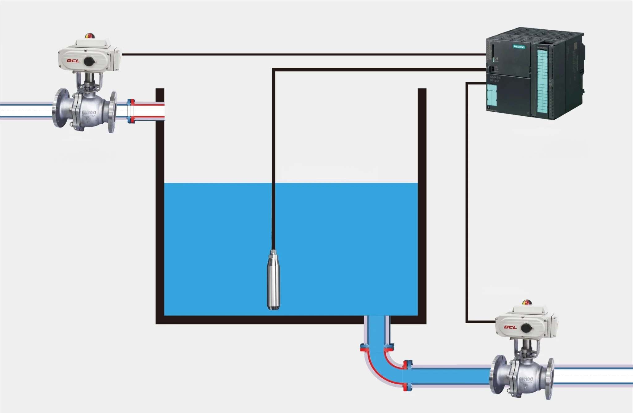
A bubbler bleeds a regulated stream of compressed air down a dip tube to the tank bottom. Back-pressure on the dip tube equals the hydrostatic head above the tube opening (same ρgh, just measured outside the tank). Bubblers win when the fluid is too aggressive or too hot for any wetted sensor, and lose when you need to maintain a clean air supply, regulator, and a dip-tube that resists clogging.
| Criterion | Hydrostatic | Bubbler | Radar | Ultrasonic | Float |
|---|---|---|---|---|---|
| Capital cost | Low | Low | High | Medium | Lowest |
| Accuracy at depth | 0.25 % FS typical | 0.5 % FS typical | 0.05 % FS achievable | 0.25 % FS | Switch-grade |
| Foam tolerance | Excellent | Good | Marginal | Poor | OK |
| Vapor / steam tolerance | Excellent | Excellent | Excellent | Marginal | OK |
| SG dependency | Direct | Direct | None | None | None |
| Install complexity | Drop probe | Air supply + regulator | Top mount, beam path | Top mount, foam clear | Mechanical |
For the DP-specific radar / guided-wave comparison with worked install cases, see DP Level Measurement H2-6.
Five limitations to flag at spec time: (1) SG dependency makes variable-product tanks a problem; (2) long vented cables need humidity desiccant service every 6–12 months; (3) condensation in the vent tube causes pressure offsets if desiccant fails; (4) submerged probes face chemical attack, and the wrong alloy halves probe life; (5) open tanks lose accuracy when surface evaporation or volatile-product loss biases the inferred head.
Installation Pitfalls That Both Configurations Share
Five problems trace back to the physics rather than the variant chosen.
- Vented reference path blocked. A submersible cable’s desiccant tube, or a DP transmitter’s atmospheric vent, needs scheduled service. Plan a 6–12 month desiccant swap. A blocked vent is the most common cause of slow drift that looks like sensor failure but is actually barometric subtraction error. Vent fittings and other gauge attachments are scoped by ASME B40.100.
- Zero-drift exceeding spec window. Chinese verification regulation JJG 882 (for pressure transmitters) sets a minimum useful range above the lower span limit. In practice, do not spec a 0–10 mH₂O transmitter when you only ever see 0.1 m of head, because the bottom 4 % is verification-uncertain territory.
- SG assumed, never confirmed. At commissioning the spec sheet says “SG 1.00 (water)” and nobody checks again. Six months later the tank holds a glycol blend at SG 1.04 and the level reads 4 % low. A 5-minute SG check during routine inspection catches this.
- Temperature compensation confused with process correction. A transmitter’s internal temperature compensation corrects the sensor‘s output for ambient changes. It does NOT correct for changing fluid density at process temperature. Two different problems; only the second requires a density meter or recalibration when product changes.
- Wrong wetted material on aggressive service. A water-treatment plant pulled 316L probes out of a sodium hypochlorite dosing tank after about 8 months of service with pitting and diaphragm thinning. Switching to the titanium-housed HM21R extended in-service life to roughly 36 months on the same duty.
For submersible-specific failure modes (lightning, vent-tube condensation, silt, cable damage, freeze, chemical attack) with full field-tech diagnostic, see our Submersible Level Transmitter Guide.
When the fluid density is not constant, as on a boiler steam drum, the hydrostatic reading needs pressure-based compensation; see boiler drum level measurement for the worked case.
FAQ
What are the limitations of hydrostatic pressure level measurement?
Five real limits: density-dependent error if SG drifts, barometric error if the vented reference fails, long-cable humidity service every 6–12 months, chemical attack risk that depends on diaphragm alloy, and accuracy decay if surface evaporation skews the apparent column.
What is the difference between a hydrostatic level sensor and a DP level transmitter?
Same physics (P = ρgh), different configuration. A hydrostatic probe sits inside the liquid; a DP transmitter sits on a side flange and reads the same column via a differential reference port. The choice usually falls out of whether the tank is open or sealed. See our DP Level Measurement guide for the full walk-through.
How accurate is hydrostatic level measurement?
Field-typical for a quality submersible probe is around 0.25 % FS on the calibrated range, before SG and temperature corrections. The bottom 4 % of range carries higher relative error and should be left out of normal operating spans (see JJG 882 verification logic in H2-8).
Can hydrostatic measurement work with foam or boiling liquid?
Yes for foam: hydrostatic ignores surface conditions and reads the column underneath, which is why it outperforms ultrasonic on foaming sumps. Boiling liquid is trickier; at saturation the column density is not constant, so calibrate at expected operating temperature and accept that startup transients read off-scale.
If you are speccing a hydrostatic level setup, the right starting point depends on where in our cluster you land: Submersible deep-dive — Submersible Level Transmitter: 6 Failure Modes That Destroy Accuracy. DP transmitter deep-dive — DP Level Measurement: Principle, Setup & How to Pick. Calculator — punch your numbers in our hydrostatic pressure calculator.
For dirty or corrosive tanks where a submerged sensor would fail, a non-contact bubbler (purge) level method keeps the transmitter out of the process entirely.
Spec a hydrostatic setup? Match common service: fresh water → HM21; sodium hypochlorite → HM21R; remote tanks → HM210 wireless.