Inches of Water Column to PSI: Conversion + HVAC & Gas Specs
If you read HVAC drawings or commission gas appliances, you will keep running into a pressure unit that looks awkward at first sight: inches of water column. The notation switches between inWC, inH2O, inWG, inAq, and the "WC mark depending on whose datasheet you are holding, and the numeric value is always tiny compared to PSI. That smallness is the entire point. The unit exists so ductwork, gas regulators, and filter pressure drops can be specified at useful resolution. In this guide I walk through the definition, the inWC to PSI conversion (with a quick-reference card), real furnace and duct numbers, and when a permanent differential-pressure transmitter beats a handheld manometer.
What Is Inches of Water Column?
One inch of water column (1 inWC) is the pressure produced by a vertical column of water exactly one inch tall, at a reference temperature of 4 degC (39.2 degF) and standard gravity. The 4 degC reference is conventional because pure water reaches its maximum density (1000 kg/m³) there, which makes the math clean.
Plug those numbers into pressure = density × gravity × height:
1000 kg/m³ × 9.80665 m/s² × 0.0254 m = 249.089 Pa
That value matches NIST SP811. For day-to-day work most engineers just remember 1 inWC ≈ 249 Pa ≈ 0.0361 psi.
inWC is a gauge measurement. Every reading zeros out atmospheric pressure first. Always re-zero a manometer before each use; otherwise elevation and barometric drift shift the baseline.
How inWC Compares to PSI, Pa, kPa, and mbar
The conversion engineers reach for most often is inWC to PSI. The exact factor:
1 inWC = 0.0361273 psi. Inverted: 1 psi = 27.708 inWC.
That second number is the one to commit to memory. For a primer on the PSI pressure unit itself, see the dedicated overview. A 0.5 inWC duct loss equals 0.018 psi. That value is too small to resolve on a standard PSI gauge, which is exactly why HVAC stays on inWC.
| From 1 inWC (4 degC) | Equivalent |
|---|---|
| Pascals (Pa) | 249.089 Pa |
| Kilopascals (kPa) | 0.249089 kPa |
| Millibar (mbar) | 2.4909 mbar |
| PSI | 0.036127 psi |
| mmH2O (4 degC) | 25.4 mmH2O |
| inHg (0 degC) | 0.07356 inHg |
Worked example. A natural-gas furnace manifold spec of 3.5 inWC equals:
- 3.5 × 249.089 = 872 Pa
- 3.5 × 0.0361 = 0.126 psi
- 3.5 × 2.4909 = 8.72 mbar
For multi-unit checks during a service call, our pressure unit converter handles inWC, mmH2O, Pa, kPa, mbar, PSI, inHg, and bar in one screen. For higher-range PSI work, see our gauge pressure formula walkthrough.
One caveat the table hides: the 4 degC reference matters at the third decimal place. A reading taken at 20 degC and labelled inWC differs by about 0.1 percent. Invisible for HVAC duty, audible for custody-transfer flowmeters. I unpack this in the notation section below.
Why HVAC and Gas Use Inches of Water Column
The honest answer is resolution. A typical residential supply duct runs at 0.2 to 0.6 inWC of static pressure. Converted to PSI that span is 0.007 to 0.022 psi. No truck-grade PSI gauge reads usefully at that resolution.
inWC also carries historical inertia. Every North American furnace, gas regulator, and filter datasheet since the 1960s uses it, and the instrument supply chain (Magnehelic, digital manometers, Dwyer Mark II) was built around it. Outside North America the same low-pressure values are reported in mmH2O or Pa: 1 inWC = 25.4 mmH2O ≈ 249 Pa.
Furnace Gas Pressure Specs in inWC
Combustion appliances are the second place inWC dominates. Gas regulators step utility pressure down to a manifold pressure low enough to feed burner orifices safely, and the whole tuning happens in fractions of an inWC.
| Spec | Natural Gas (NG) | LP / Propane |
|---|---|---|
| Inlet (utility → gas valve) | 7–10 inWC | 11–13 inWC |
| Manifold (valve → burner, running) | 3.5 inWC | 10–11 inWC |
| Equivalent in PSI | 0.126 psi | 0.397 psi |
| Equivalent in kPa | 0.872 kPa | 2.74 kPa |
A 0.5 inWC drift on a 3.5 inWC NG manifold is 14 percent off the setpoint. Manifold pressure feeds gas flow through fixed-area orifices, so a deviation that large pushes combustion outside the manufacturer’s tuned band, with sooting or short-cycling as the visible symptoms.
Cross-market check. China’s GB 16410-2020 Domestic Gas Cooking Appliances sets household NG inlet at 2.0 kPa = 8.03 inWC and LP at 2.8 kPa = 11.24 inWC, almost identical to the US figures. A Chinese-built rooftop unit specced at 2.0 kPa reads as 8 inWC on a US manometer with no rework.
Duct Static Pressure in inWC: What’s Normal
Duct static pressure is the resistance a blower fights to move conditioned air. It is read across two points (typically supply and return plenum) and reported as Total External Static Pressure (TESP) in inWC.
Common reference ranges I keep on a field card:
- Residential split system (rated): ~0.5 inWC TESP
- Residential restricted airflow (action needed): ≥0.9 inWC
- Light commercial RTU: 0.5–0.8 inWC TESP
- Filter drop (clean → dirty): 0.1 → 0.25 inWC
- Cooling coil drop: 0.20–0.40 inWC
- Cleanroom adjacent zones: 0.03–0.05 inWC ΔP
- CDC airborne isolation room (negative): ≥0.01 inWC relative to corridor
The CDC’s HICPAC infection-control guidance requires a minimum of 0.01 inWC (≈2.5 Pa) of negative pressure between an airborne-isolation room and its anteroom. That single number drives every micro-DP monitor in hospital corridors.
For the full field procedure to measure TESP, see our how to measure static pressure in HVAC six-step guide. For sensor selection, our low-pressure transducer guide walks through range and accuracy tradeoffs for HVAC duty.
How to Measure inWC: Manometers, Magnehelic & DP Transmitters
Four instrument families read inWC. They are not interchangeable.
| Instrument | Best use | Typical accuracy |
|---|---|---|
| U-tube water manometer | Calibration / training | ±0.1 inWC |
| Magnehelic dial gauge | Panel-mount visual, spot checks | ±2 % FS |
| Digital handheld manometer | Field commissioning, two-port ΔP | ±0.5 % rdg |
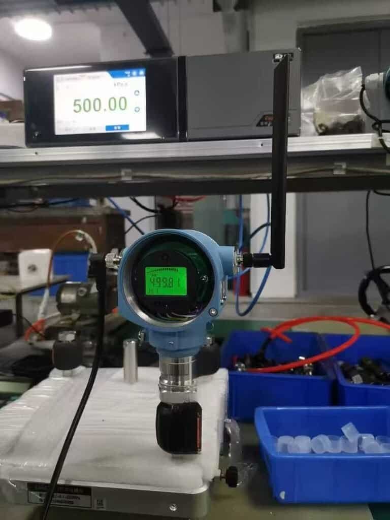
| DP transmitter (4-20 mA) | Permanent monitoring, SCADA, alarming | ±0.075–0.25 % FS |
Accuracy figures above are vendor-typical bands for each instrument family; always confirm the specific datasheet of the model you specify.
The Chinese national calibration regulation JJG 882-2019 Pressure Transmitters caps total uncertainty at 1 % FS for low-range DP transmitters. A handheld is the right tool for a quarterly site walk. The moment the reading needs to feed an alarm relay, a BMS trend, or a tenant-billing dashboard, the handheld is wrong. It lives in your truck. That is the cue for a permanent transmitter.
When to Use a DP Transmitter Instead of a Handheld Manometer
Five triggers say a project has outgrown the handheld:
- 24/7 monitoring — anything that needs a trend graph, not a single value.
- BMS / SCADA — controller needs live 4-20 mA or HART.
- Alarming — restricted filter, blocked coil, lost duct seal, isolation-room breach.
- Predictive maintenance — filter slope over months, fan-curve drift.
- Hazardous or hard-to-reach location — above hard ceilings, intrinsically-safe zones.
Three HMK SKUs span the inWC range you encounter in HVAC duty:
| Model | Range in inWC | Best fit |
|---|---|---|
| HM30 Micro DP | 0–2 inWC (0–500 Pa) | Cleanroom ΔP, isolation room, low-leak duct |
| HM31 DP | 0–40 inWC and up (0–10 kPa to 2 MPa) | Filter banks, coils, general HVAC duct |
| HE30 Wind/DP | Pitot tube + duct static | Fan-curve diagnostics, VAV airflow stations |
Field example. An East-China electronics fab needed an ISO 5 cleanroom held at 0.05 inWC (≈12 Pa) positive to its ISO 7 gowning corridor. We installed two HM30 transmitters in parallel, fed both into the building’s Modbus loop, and trended the signal at one-minute resolution for 12 months. Combined drift over the year sat at ±0.005 inWC, well inside the cleanroom protocol’s 10 percent-of-setpoint tolerance. A handheld would have required a tech walking the corridor every shift; the transmitter pair did the same job unattended and threw a deviation alarm before any batch was at risk.
Notation & Temperature Pitfalls
Notation. The same unit travels under several abbreviations: inWC and the "WC mark dominate North-American HVAC datasheets; inH2O and "H2O appear on pressure-sensor datasheets and scientific work; inWG and "WG live on older mechanical drawings and UK ventilation specs; inAq and "Aq turn up in British boiler and steam specs. If a spec sheet says 0.5 "WG and your sensor catalog reads inWC, they are the same number.
Reference temperature. The 4 degC convention is global default, but US gas-measurement and custody-transfer work sometimes uses 60 degF (15.6 degC) or 20 degC. The numerical difference is small (≈0.1 percent), invisible in HVAC, audible at custody-transfer accuracy. Mnemonic: spec sheet, assume 4 degC; calibration cert, find the temperature line.
FAQ
How many inches of water column equal 1 psi?
27.708 inWC = 1 psi. Reversed, 1 inWC = 0.0361 psi.
What should my natural-gas furnace manifold pressure be?
About 3.5 inWC when the burner is firing, with 7–10 inWC inlet to the gas valve. LP propane runs 10–11 inWC manifold and 11–13 inWC inlet. Verify against the nameplate before adjusting.
Is inH2O the same as inWC?
Yes. Same unit, different abbreviation. inH2O, inWC, inWG, inAq, and the inch-of-water symbol all denote the same physical quantity at the same 4 degC reference unless stated otherwise.
What tool measures inWC?
For spot checks, a digital handheld manometer (±0.5 % rdg). For continuous monitoring, a 4-20 mA DP transmitter such as the HM30 (0–500 Pa) or HM31 (0–10 kPa).
What is a normal HVAC duct static pressure?
0.5 inWC TESP for a typical residential split system. Above 0.9 inWC signals restricted airflow, usually a dirty filter, clogged coil, or undersized return.
Next step: Send your spec sheet for a model recommendation in 24 h. Get in touch →
Need a low-range DP transmitter for inWC duty?
Browse HMK low-pressure transducers → Or contact our application desk for a sizing review on your duct, cleanroom, or gas-monitoring spec.