Supply Pressure Gauge: What It Does and Where to Spec It
The phrase “supply pressure gauge” lands in three different places: a pneumatic regulator panel in a chemical plant, a hydraulic power unit driving a press, and a CDL pre-trip walk-around on a Class A truck. Same physics, different decision rules. This guide answers what the gauge is telling you and what it should read in your application, with five spec tables. Spec engineers, jump to section 3 and 4. CDL drivers, jump to section 9.
What a Supply Pressure Gauge Actually Measures
A supply pressure gauge measures the upstream pressure feeding a regulator, valve actuator, hydraulic load, or air-brake reservoir: the raw power available before any control element shapes it.
- Pneumatic system: the supply gauge sits on the compressed-air main feeding a regulator, typically 80–100 psi.
- Instrument air: it reads the air-prep manifold output before the 3–15 psi control signal is generated.
- Hydraulic power unit: it sits at the pump discharge, reading 1,500–3,500 psi raw pressure.
- CDL airbrake: it reads the air-tank reservoir, separate from the application gauge that reads brake-chamber pressure during a pedal press.
A supply gauge reads available power, not delivered work. If it drops, your source or upstream piping is the problem.
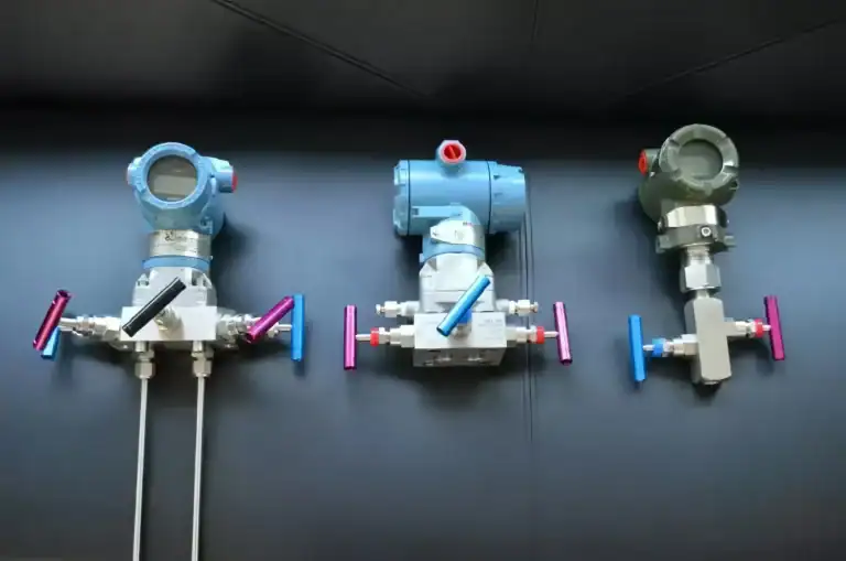
Supply vs Output (Application) Gauge: Two Sides of One Regulator
On a regulator with two gauges, the inlet gauge reads supply, the outlet gauge reads what the regulator delivers. A 100 psi shop main feeding a 25 psi spray-gun setpoint shows 100 on the inlet and 25 on the outlet, with or without flow.
| Dimension | Supply (Inlet) | Output (Application) |
|---|---|---|
| Position | Upstream of the regulator | Downstream of the regulator |
| Range | High, tracks the source | Low, capped by setpoint |
| Behavior | Drifts with main pressure | Holds steady at setpoint |
| If it drops | Source, leak, or filter upstream | Regulator wear or downstream load |
| Typical reading | 60–100 psi (shop air) | 3–15 psi (signal) or 25–80 psi (tool) |
The mistake I see most often on plant walks: a tech sees the supply gauge sagging and blames the regulator. Nine times out of ten, the regulator is fine; the upstream filter element is loaded, the dryer is icing up, or a parallel branch just opened a high-flow load. Confirm by capping downstream demand and watching whether the supply gauge climbs back.
Supply Gauge Types: Mechanical, Electronic, or Transmitter
Three families show up in the field, sometimes in parallel on the same panel.
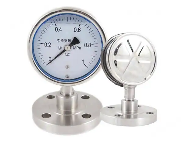
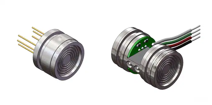
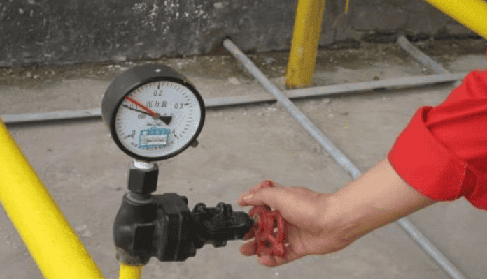
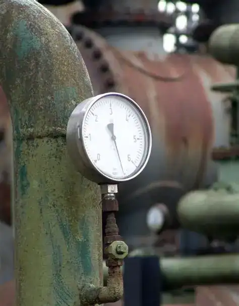
Mechanical (Bourdon-tube). A C-shaped tube straightens under pressure and drives a geared needle. No power, no wires, vibration-tolerant with glycerin or silicone fill. Accuracy ±2% FS, ±1% on test gauges. The default for local indication.
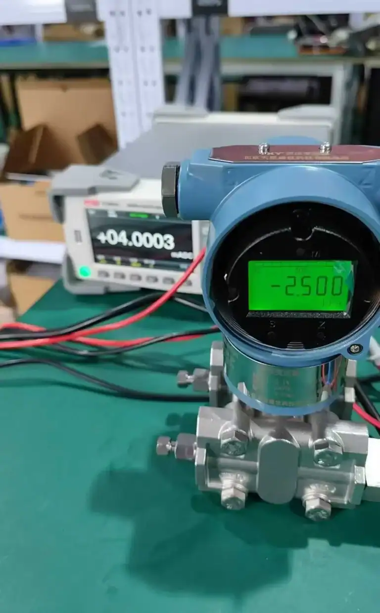
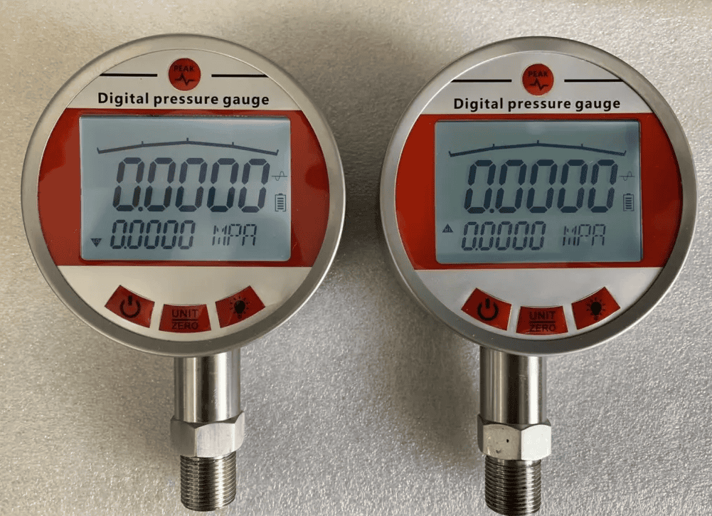
Electronic (digital) indicator. Piezoresistive or capacitive sensor driving a digital readout, battery or 24 VDC. Accuracy ±0.25% FS; many add max-hold or peak-capture. Higher resolution, still local.
Pressure transmitter (4-20 mA / HART). Same sensor, output is a current loop back to a PLC, DCS, or SCADA. Accuracy ±0.1%. Adds remote alarming, logging, and SIL2 versions. The choice when the data has to leave the panel; see section 8.
Typical PSI Ranges by Application: Spec Reference Table
The single question I hear most: “what should this gauge read?” These five contexts cover ~95% of supply-gauge readings in the field.
| Application | Typical Supply Range | Warning / Action Threshold | Standard |
|---|---|---|---|
| Pneumatic actuator (industrial) | 60–100 psi | <50 psi: actuator stalls | ISA-7.0.01 |
| Instrument air (control loop main) | 80–100 psi (main); 3–15 psi (signal) | <70 psi: reduce demand | ISA-7.0.01 / ISA-S7.4 |
| Hydraulic power unit | 1,500–3,500 psi | >10% above setpoint: relief check | NFPA T2.3 |
| CDL airbrake reservoir | 100–125 psi (cutout) | 55–75 psi: low-pressure warning | FMVSS 121 / 49 CFR 393.51 |
| RV / domestic water supply | 40–80 psi (regulator-limited) | >80 psi: line damage risk | IPC 2018 / RVIA |
The reading rhythm matters as much as the absolute number. On a steady system the supply gauge should hold within ±2 psi of nominal. A swing greater than 5% of the working range signals upstream pulsation, undersized piping, or a loaded filter, not a gauge fault.
One trap on the instrument-air row: the 80–100 psi supply main and the 3–15 psi pneumatic control signal are both “instrument air,” but they sit on different sides of the air-prep package. The gauge labelled “supply” almost always means the main.
P&ID Symbol and Tag Conventions
On a P&ID, a supply pressure gauge does not get a special symbol. The ANSI/ISA-5.1-2009 standard uses the same circle for any local pressure indicator, with the tag inside. What identifies it as supply is the tag and the line it taps.
The first letter is the variable (P for pressure), the second is the function: G (gauge), I (indicator), T (transmitter). A typical local supply gauge is tagged PG-101. If your site convention adds a service descriptor, it becomes PG-AS-101 for air supply, PG-IA-101 for instrument air, or PG-N2-101 for nitrogen.
When the supply line drives a transmitter back to the control room, the tag becomes PT-101, drawn as a circle with a horizontal line through it (the signal line).
How to Read It Correctly: Three-Step Procedure
Most field misreads come from skipping one of three steps.
Step 1. Read at eye level. A bourdon gauge can read 2 psi off if you look down at the dial. Parallax is the largest single source of “wrong” gauge readings on plant audits I run. If the gauge is mounted high or low, install a mirror or a 90° elbow.
Step 2. Confirm zero before you trust the reading. With the system isolated and vented, the needle should sit at the zero peg. If it drifts, the C-tube has taken a permanent set; replace the gauge.
Step 3. Compare against the section 4 spec table. A reading inside nominal is fine; outside the warning threshold means upstream investigation. Do not adjust setpoints or replace components before steps 1 and 2 confirm the gauge is honest.
Troubleshooting: Low, Dropping, or Fluctuating Readings
Most “the supply gauge is acting up” calls turn out to be one of five problems. The pattern of the reading tells you which.
| Symptom | Probable cause | Fix |
|---|---|---|
| Low and steady | Source under-spec, undersized piping, loaded filter | Check compressor cutout, verify line size, change filter |
| Drops over a shift | Slow leak in supply manifold or downstream branch | Soap-test joints, ultrasonic leak detector |
| Bounces > 5 psi | Pulsating source (recip compressor, ram pump) without snubber | Add a snubber or pulsation dampener at the gauge tap |
| Climbs above source | Regulator stuck closed downstream, or thermal expansion in a dead-headed leg | Vent the trapped volume, inspect the regulator |
| Dead at zero | Iso valve closed, mechanism failed, or sensing port plugged | Check the iso valve first, then swap the gauge |
A short tool kit keeps diagnosis under thirty minutes: a reference gauge of the same range, a digital multimeter, a soap bottle, and the iso valve key. Fluctuation that tracks engine RPM or compressor cycle is a source-side issue. Random fluctuation with no driver pattern is usually the gauge or wiring.
Choosing Between Mechanical, Electronic, and Transmitter Versions
Once you know your supply range and read the gauge correctly, the next question is which form factor to install. The trade-off is between cost, accuracy, and whether the data has to travel.
| Dimension | Mechanical (Bourdon) | Electronic Indicator | Transmitter (4-20 mA / HART) |
|---|---|---|---|
| Accuracy | ±2% FS | ±0.25% FS | ±0.1% FS |
| Remote access | None | None (local only) | PLC / SCADA / DCS |
| Power | None | Battery or 24 VDC | 24 VDC loop |
| Alarming / logging | None | Limited (max-hold) | Full, SIL2 available |
| Relative cost | 1× | 3–5× | 8–15× |
| When to choose | Simple local monitoring | Vibration + need for ±0.25% | Remote, audit trail, or SIL |
A short upgrade rule: replace a mechanical gauge with a transmitter when any of the following is true.
- The system feeds SCADA, a PLC, or a DCS.
- You need historical trends or alarm audit logs.
- High- or low-pressure interlocks are required (IEC 61511 SIL2 or SIL3).
- The gauge is mounted where an operator cannot easily see it (height or hazardous area).
- Long-term accuracy better than ±0.25% of full scale is required.
For air-supply mains and regulator panels, a 4-20 mA pressure transmitter drops in with standard two-wire wiring. Hazardous-area panels should use the intrinsically safe Ex-i variant.
CDL Airbrake Context: One Phrase, Two Worlds
If you came here studying for a CDL exam, the same words point at a different system. On a Class A or B truck, the supply pressure gauge reads the air-tank reservoir, separate from the application gauge that reads brake-chamber pressure during a pedal press.
| Item | Spec |
|---|---|
| Build pressure (cutout) | 100–125 psi |
| Cut-in pressure | 80–105 psi |
| Low-pressure warning | 55–75 psi |
| Parking-brake auto-apply | 20–45 psi |
The same gauge, the same physics, different decision rules. An industrial supply main is a continuous source; an airbrake reservoir is a finite tank that the compressor refills. If you came here for CDL prep, see 49 CFR 393.51 for the regulatory text.
FAQ
What is a supply pressure gauge used for?
It indicates the upstream pressure available to a regulator, actuator, hydraulic load, or air-brake reservoir: the raw power feeding the system before any control element shapes it. See section 1.
What are the two types of pressure gauges?
The split most people mean is mechanical (Bourdon-tube) versus electronic (digital indicator or transmitter). Mechanical needs no power and reads ±2% FS; electronic reaches ±0.1% and can send data to a PLC. See section 3 for the full three-family breakdown.
What does the supply pressure gauge tell the driver in a CDL pre-trip?
It tells the driver how much compressed air is in the reservoir. The cutout is 100–125 psi; a warning trips at 55–75 psi; the parking brake auto-applies at roughly 20–45 psi. See section 9.
Why is my supply pressure gauge reading low?
Five usual causes: source under-spec, loaded filter, slow leak, pulsation without a snubber, or a closed isolation valve. The pattern of the reading narrows it. See section 7.
When should I replace a mechanical supply gauge with a 4-20 mA transmitter?
When the data has to leave the panel: SCADA, audit trail, SIL interlocks, or a gauge mounted out of sight. See section 8.
Can a supply pressure gauge show negative pressure?
A standard supply gauge cannot. Its range starts at zero and reads positive only. Vacuum or compound gauges read below zero. The “negative mmHg” wording you may have seen belongs to medical blood-pressure measurement, not industrial supply gauges.
Related reading: For the broader temperature-gauge primer covering definition, sensing types, and selection criteria, see Temperature Gauge: Definition, 5 Types, and Selection Guide.
Supply-pressure indication typically uses Cl 1.6 or Cl 2.5 since the gauge is monitoring a steady utility line. For how to pick the right accuracy class for a given application, see Pressure Gauge Accuracy Class.
Need this read remotely? Compare HMK 4-20 mA / HART supply transmitters for pneumatic, hydraulic, and instrument-air panels. Send your spec sheet for a model recommendation in 24 h.