Smart Pressure Transmitter: How It Works and When to Use One
When a lead engineer tells you to put a smart transmitter on that loop, the word doing the work is smart, and it is rarely defined. You already know how a 4-20 mA pressure transmitter behaves: pressure goes up, current goes up, the DCS reads it.
What you have to decide is whether the extra cost of a microprocessor-based unit buys anything your loop will actually use. The answer depends on what sits inside the housing, and on what your control system can read.
What actually makes a transmitter “smart”
A smart pressure transmitter processes its measurement with an onboard microprocessor before the signal leaves the housing, and it can talk back to a host over a digital protocol. That is the full definition.
The sensing element can be any of the usual technologies: a diffused-silicon cell, a ceramic capacitive diaphragm, or a silicon-on-sapphire chip. If you want to compare those raw sensors, the pressure transmitter working principle guide covers the four types. What the smart label adds sits downstream of the sensor: digital processing, stored calibration data, and two-way communication.
Put plainly, a conventional analog transmitter measures and outputs. A smart transmitter measures, corrects itself in software, and reports on its own condition. The pressure port and the wetted parts can be identical. What differs is everything that happens to the signal after the diaphragm moves.
Inside a smart transmitter: the signal chain
A smart transmitter holds a tighter accuracy figure because its signal takes a longer, more corrected path than an analog unit’s. Every claim you read about accuracy and long-term stability traces back to this sequence.
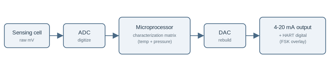
The sensing cell produces a small, raw electrical signal that is neither linear nor temperature-stable on its own. An analog-to-digital converter turns that signal into numbers.
The microprocessor then applies the correction that does the real work. At the factory, a technician measures each transmitter at many combinations of temperature and pressure, against references traceable to a national standard such as NIST, and stores the error at every point in a characterization matrix held in nonvolatile memory.
In service, the processor reads the current temperature, looks up the correction for the pressure it sees, and cancels the error before it outputs the reading. A digital-to-analog converter then rebuilds a clean 4-20 mA signal, and a HART modem can add digital data on top.
An analog transmitter has no equivalent step. The factory trims it once, usually at room temperature, so any drift with temperature or over the years shows up directly in the output.
That single difference, multi-point digital characterization against one-point analog trim, explains the accuracy gap. It is why smart units such as HMK’s HM29 hold 0.05% of full scale where a basic analog unit runs several times looser.
Smart vs conventional analog transmitters
The differences that matter follow from that signal chain rather than from a spec sheet. The table below compares the two on the criteria that change a purchasing decision.
| Criterion | Conventional analog 4-20 mA | Smart (microprocessor-based) |
|---|---|---|
| Output | Single analog value only | 4-20 mA plus digital data on the same wires |
| Accuracy over temperature | Limited by one-point trim, drifts | Held by stored characterization, far more stable |
| Rangeability (turndown) | Narrow, typically 5:1 to 20:1 | Wide, commonly around 100:1 |
| Re-ranging | Adjust zero and span in the field, by hand | Reconfigure remotely from the control room |
| Diagnostics | None; a fault looks like a bad reading | Self-diagnostics report the fault by name |
| Cost | Lower unit price | Higher unit price, lower lifecycle cost on critical loops |
The rangeability row is where smart units quietly save money. A wide turndown means one part number covers many ranges. You can reconfigure a wide-span unit to read a small span accurately, so a single spare on the shelf replaces transmitters across several loops instead of one.
The output signal guide explains how the 4-20 mA layer itself behaves once you have chosen a transmitter type.
HART, RS485 and Modbus: what “digital” really means
Many engineers treat smart and HART as the same thing. They are not. Underneath all of them sits the 4-20 mA current loop, the baseline of ISA signaling practice for decades. HART is one digital protocol layered on that loop, and a smart transmitter may offer others instead of it, or alongside it.
| Protocol | What it is | Wiring | Typical use |
|---|---|---|---|
| 4-20 mA | Analog current, one value | Two wires | Simple loops, local indication |
| HART | Digital data layered on the 4-20 mA loop using frequency shift keying | Same two wires as 4-20 mA | Keep the analog loop, add config and diagnostics |
| RS485 / Modbus RTU | A purely digital serial bus | Separate twisted pair, many devices on one line | Digital-only networks, multidrop, PLC and SCADA polling |
HART is the low-disruption upgrade. It rides on top of the existing 4-20 mA signal, so you keep the analog reading your control system already trusts and gain digital configuration without pulling new cable.
RS485 with Modbus RTU works differently. It drops the analog signal and puts many transmitters on one digital bus, which suits a PLC or SCADA system polling dozens of points.
The rule is short. If you are keeping an existing 4-20 mA loop and only want configuration and diagnostics on top, choose HART. If you are building a digital-only network with many points on one line, choose RS485 with Modbus. If your DCS or PLC understands only one of them, that settles it.
HMK’s HM29 offers HART, RS485 and 4-20 mA on the same platform, so one product line serves both an analog-plus-HART plant and a digital multidrop network. The 4-20 mA current loop explainer covers the mechanics of the loop itself.
One practical catch deserves attention before you commit to HART. The protocol carries its data as two audio tones on the loop, 1200 Hz for a digital one and 2200 Hz for a zero, following the Bell 202 standard.
If a variable-frequency drive nearby runs a carrier frequency or harmonics inside that band, it can disturb HART communication. That is why transmitters intended for drive-heavy plants are built and wired with extra shielding. HART still works in those plants. You simply specify the shielding up front instead of discovering the problem at commissioning.
Remote re-ranging, diagnostics and characterization
The features that pay for a smart transmitter are the ones that save a trip to the field. Remote re-ranging lets you change zero and span from the control room, so a level or flow loop that needs its range shifted no longer requires anyone to climb to the transmitter and turn a screw.
Self-diagnostics work the same way. When something goes wrong, the transmitter names the reason, such as a sensor open circuit, a temperature outside limits, or an electronics fault, instead of simply drifting. That turns a half-day fault hunt into a targeted repair.
Digital characterization is the feature you never see but rely on most. Because the correction data is stored and applied continuously, a smart transmitter holds its accuracy across temperature swings and over years of service far better than an analog unit trimmed once. On a loop where recalibration means a shutdown, that stability is often worth more than the headline accuracy number.
When analog 4-20 mA is the right call
Smart is not automatically better. HMK sells both a straightforward analog unit, the HM20 general-purpose transmitter, and the smart HM29, so what follows is not a sales position.
A conventional analog transmitter is usually the right choice in four situations:
- the loop runs a fixed range that will not change;
- the reading only drives local indication or a simple alarm;
- no DCS or PLC on the loop can read digital data;
- the loop count is small and maintenance access is easy.
In those cases the diagnostics and remote configuration have nothing to act on, so paying for them adds cost without adding value.
Take a utility water line with a permanent 0 to 10 bar range and a panel gauge as its only reader. An analog HM20 does everything that loop needs, and the HART data in a smart unit would never be polled.
A short checklist for choosing smart vs analog
You can settle most cases with a short list. Count how many of these describe the loop in front of you:
- The loop is critical, and unplanned downtime on it is expensive.
- The control system speaks a digital protocol, whether that is HART on the existing 4-20 mA loop or Modbus over RS485 on a digital bus.
- The range may need to change, or one spare should cover several ranges.
- Maintenance staff are stretched, and remote configuration would save field trips.
- Long-term stability matters because recalibration means a shutdown.
If you answer yes on the second point, decide the protocol early: HART if you are keeping the analog loop, RS485 with Modbus if you are building a digital-only network. That choice narrows the model list before anything else does.
If four or more are true, specify a smart transmitter. If two or three are true, fit smart units on the critical loops and leave the rest analog. If one or none are true, a conventional analog transmitter is the sound, economical choice.
Most plants end up mixed for exactly this reason. The same loop-by-loop logic runs through the oil and gas pressure instrumentation guide.
Smart pressure transmitters by HMK TECH
For loops that call for a smart transmitter, HMK offers two units built on the architecture described above.
The HM29 Digital Intelligent Pressure Transmitter holds an accuracy of 0.05% of full scale and supports HART, RS485 (Modbus RTU) and 4-20 mA on the same platform. Its ranges run from a few kPa up to about 100 MPa, so one product line serves both analog-plus-HART loops and digital multidrop networks.
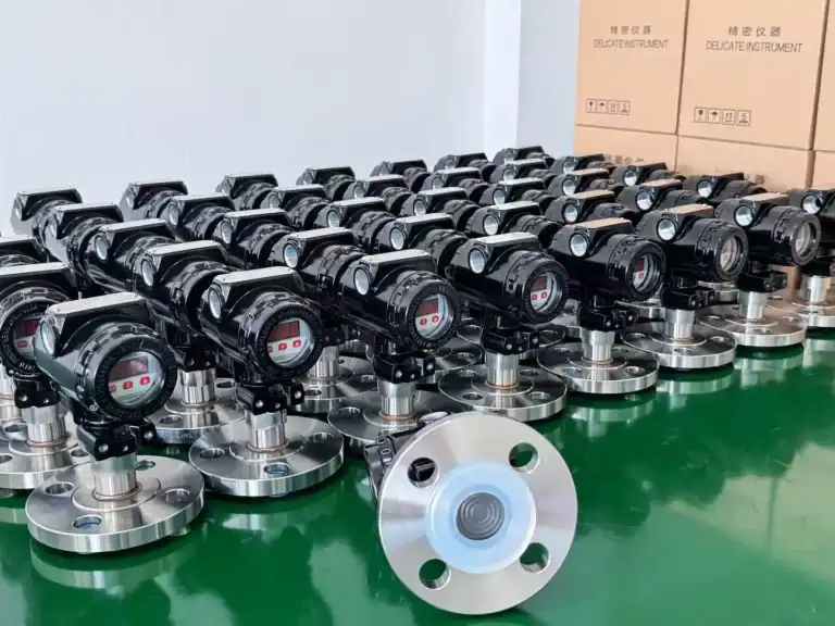
The HM3051 Smart Differential Pressure Transmitter brings the same digital processing to differential pressure work, with HART communication and an accuracy of ±0.1%, for flow and level applications that benefit from remote re-ranging. Both units apply the stored multi-point characterization that gives a smart transmitter its stability, and both can be specified to the range and process connection your loop needs.
Frequently asked questions
What is a smart pressure transmitter?
It is a pressure transmitter whose reading is processed by an onboard microprocessor and which communicates over a digital protocol such as HART or Modbus. The processor applies stored calibration corrections and reports device status, so the transmitter both measures pressure and manages its own accuracy and diagnostics.
What is the difference between a smart and an analog pressure transmitter?
An analog transmitter outputs a single 4-20 mA value from a one-point calibration. A smart transmitter digitizes the signal, corrects it against a stored multi-point characterization, and adds digital communication, giving tighter accuracy, wider rangeability, remote configuration and self-diagnostics.
Does a HART pressure transmitter need new wiring?
No. HART layers a digital signal on top of the existing 4-20 mA loop using frequency shift keying, so it uses the same two wires. You need a HART-capable host, handheld communicator or input card to read the digital data, but no new cable.
How accurate is a smart pressure transmitter?
It depends on the model, but smart units are typically several times more accurate and more stable than analog equivalents because of digital temperature and pressure characterization. HMK’s HM29, for example, is specified at 0.05% of full scale.
Is HART the same as RS485 or Modbus?
No. HART keeps the analog 4-20 mA signal and adds a digital layer on the same wires. RS485 with Modbus RTU is a purely digital serial bus on a separate pair that carries no analog signal and supports many devices on one line. A transmitter may offer one, the other, or both.