Boiler Drum Level Measurement: DP, Density & Shrink-Swell

On a steam drum, the water level is the one measurement you cannot afford to get wrong. Let it climb too high and you carry water over into the superheater and turbine; let it fall too low and you uncover the tubes and risk overheating and a tube failure. Most plants still infer that level from a differential pressure (DP) transmitter, and for good reason. Because a steam drum runs hot, that cell is really a differential pressure transmitter for hot service, rated for the temperature it sees at the taps. A DP cell is rugged, repairable, and sits behind the same isolation valves your operators already trust. The catch is that a steam drum breaks the one assumption a DP level measurement quietly depends on, a constant fluid density. This guide covers how to read drum level with a DP transmitter and how to size and compensate it with real steam-table numbers. It also explains why the level can appear to move the wrong way on a load swing, and when a different technology is genuinely the better call.
For the general theory of inferring level from head pressure, see our DP level measurement guide and the physics of hydrostatic level. This article stays on the steam drum, where the rules change.
Drum level is the boiler’s most safety-critical measurement
A boiler drum separates saturated water from saturated steam at the same pressure and temperature. The control system holds the water at a target level by trimming feedwater against steam demand. Two failure directions matter, and they are not symmetric. A high level shrinks the steam-release area and lets droplets carry over, eroding turbine blades and tripping conductivity alarms downstream. A low level exposes the steam-generating tubes; with the heat still on, metal temperature climbs fast and you are minutes from a tube rupture. Because the consequences are this severe, boiler codes treat drum level as a protected measurement rather than an ordinary process loop, and that shapes every decision below, from how you compensate the transmitter to how many independent measurements you install.
How a DP transmitter reads level across a steam drum
The measurement is hydrostatic. You tap the drum at two points, one in the steam space near the top and one in the water space near the bottom, a fixed distance L apart. The DP transmitter compares the pressure at the two taps; the difference reflects how much of that fixed span is filled with dense water versus light steam, which is the level.
The upper tap cannot stay full of steam back to the cell, because steam would condense unpredictably in the impulse line. So the high side is run as a wet reference leg: a small condensate pot at the top keeps that leg permanently flooded with cool condensate of a known, stable density. The lower tap connects to the variable leg. As drum level rises, the variable leg gets heavier and the differential falls, so a drum-level DP loop is typically reverse-acting with a suppressed (elevated) zero. Getting that reference leg filled and kept full is half the job; the impulse-line rules in our impulse line field guide apply directly here.
The density trap: why constant-SG calibration under-reads a hot drum
Here is where it fails. A standard DP level calibration treats the process fluid as one fixed density. In a cold tank that is fine. In a steam drum it is not, because the water in the drum is saturated, and saturated water is far lighter than the cold water you used when you bench-calibrated the cell.
Water boiling at about 90 bar(g) sits near 580 °F and is only roughly 70 percent as dense as water at 100 °F. If you calibrate the transmitter as though the drum holds cool water and then run it hot, the column of hot water produces less head than the instrument expects. The indicated level then reads low, often by 15 to 25 percent of span at full level. Operators who do not know this end up running the drum far below its true safe level “to be safe.” Running a drum needlessly low wastes boiler capacity, and good instrumentation should remove that guesswork rather than reward it. The fix is not a better cell. It is compensating for the real, pressure-dependent density of both the water and the steam.
Pressure-based compensation, worked at 45 bar(g)
The useful property of a saturated drum is that you do not need a separate temperature measurement. At saturation, temperature is fixed by pressure, so once you know the drum pressure you can read the saturated water density and saturated steam density straight from a steam table. That is why drum pressure, not drum temperature, is the right compensation input.
Take a common industrial drum at 45 bar(g) with taps 800 mm apart, and pull the saturated properties from standard steam tables (the underlying formulation is the IAPWS-IF97 release):
| Quantity | Symbol | Value (45 bar(g), Tsat ≈ 259 °C) |
|---|---|---|
| Tap-to-tap span | L | 800 mm |
| Saturated water density | ρw | 785 kg/m³ |
| Saturated steam density | ρs | 23.2 kg/m³ |
| Reference-leg condensate (~40 °C) | ρref | 992 kg/m³ |
The differential the cell sees as a function of water height h above the lower tap is the reference leg minus the drum leg: ΔP = g · L · ρref − g · [ h · ρw + (L − h) · ρs ]. Evaluate the two ends:
- Empty (h = 0): ΔP = 9.81 × 0.8 × (992 − 23.2) = 7.60 kPa (≈ 776 mmH₂O), the maximum differential and the 4 mA / low-level end.
- Full (h = L): ΔP = 9.81 × 0.8 × (992 − 785) = 1.62 kPa (≈ 165 mmH₂O), the minimum differential and the high-level end.
So the calibrated span is the difference, g · L · (ρw − ρs) = 9.81 × 0.8 × (785 − 23.2) = 5.98 kPa, about 610 mmH₂O. Notice two things a constant-SG calculation gets wrong: the working span is set by (ρw − ρs), not by cold-water density, and the steam term of 23.2 kg/m³ is not negligible at pressure, so you cannot just ignore the upper part of the leg. Our DP level calibration calculator will take these densities and return the LRV and URV directly, but it is worth running the arithmetic once by hand so the suppressed zero makes sense.
Transmitter span versus DCS compensation
There are two places you can put the density correction, and the better one is usually the control system. If you let the DCS take live drum pressure, look up the saturated densities, and correct the level, then the transmitter itself should carry no density math: calibrate its span to equal the physical tap distance and let it report a clean differential. The advantage is that pressure compensation in the DCS stays correct at every pressure, including startup and shutdown when the drum is climbing through its range and a single fixed-point calibration would be wrong everywhere except one pressure.
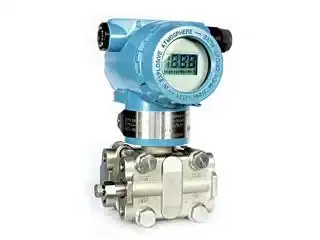
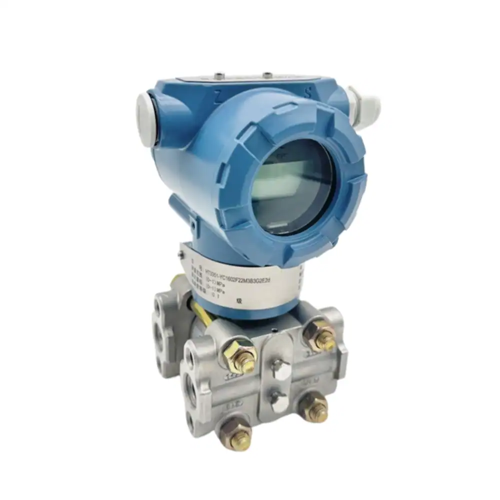
Compensating inside the transmitter at one design pressure is acceptable when the boiler runs at a steady load and rarely cycles, but it degrades as soon as the drum pressure wanders. A multivariable smart transmitter helps here because it can publish the differential and, over HART or a digital link, hand the DCS the variables it needs to close the compensation. The HM3051 smart DP transmitter is built for exactly this duty, with HART output and capacitive sensing rated for the static line pressure a drum imposes.
Shrink and swell: when the drum level lies on a load change
Even a perfectly compensated transmitter will show you a level that briefly contradicts the water mass, and operators who do not expect it will fight the instrument. This is shrink and swell, and it is real physics, not a fault.
When steam demand suddenly rises, the turbine pulls harder and drum pressure dips. Lower pressure lets the steam bubbles already suspended in the drum water expand, so the frothy mixture puffs up and the level rises, even though you are removing mass and should be adding feedwater. That is swell. On a sudden load drop the opposite happens: pressure rises, bubbles collapse, and the level falls (shrink) just as you should be cutting feedwater. A naive single-element controller reads the swell, concludes the drum is too full, and cuts feedwater at the exact moment the boiler needs more. That is how low-water trips happen during load increases. This is why drum level is almost never controlled on level alone above the smallest package boilers. Three-element control adds steam-flow and feedwater-flow signals, so the loop acts on mass balance and ignores the transient the level measurement honestly reports.
Choosing between DP, guided-wave radar, and electrode gauges
Differential pressure is the default, but it is not the only code-accepted method, and the honest comparison depends on how hard your drum cycles. Guided-wave radar (GWR) vendors will point out, correctly, that DP relies on density and that the steam-space density shifts during startup; what they sometimes leave out is that a DCS-compensated DP loop already removes that error, and that GWR has its own steam problem, the microwave pulse slows in saturated steam and needs its own reference compensation. Electrode or conductivity gauges (the Hydrastep style) read discrete points rather than a continuous level and are excellent as an independent cross-check, less so as the sole control input.
| Criterion | DP transmitter | Guided-wave radar | Electrode / conductivity gauge |
|---|---|---|---|
| Output | Continuous, analog/HART | Continuous | Discrete steps |
| Main error source | Density (solved by pressure compensation) | Steam slows the pulse (needs steam comp) | Resolution between electrodes |
| Startup / shutdown | Good if DCS-compensated | Good with steam comp | Good |
| Repairability / cost | Highest / lowest | Moderate | Moderate |
| Best role | Primary control measurement | Primary where density data is unavailable | Independent safety cross-check |
For most drums that run with a known, measured pressure, a compensated DP loop remains the most cost-effective primary measurement, and you are better off spending the GWR budget on a second, independent measurement than on replacing a DP loop that works.
Redundancy, the gauge glass, and code compliance
Because drum level is safety-critical, the boiler codes expect more than one way to see it. ASME BPVC Section I and the European water-tube standard EN 12952:2007 both call for a direct gauge glass plus independent remote measurements, and ISA practice for safety instrumented functions pushes the same way. Keep the direct-reading gauge glass (or a bicolor port) as the operator’s physical reference. Provide at least two independent remote measurements feeding control and protection. Diversity matters here: pairing a compensated DP loop with an independent electrode gauge guards against a shared failure mode that two identical DP cells would not. On the drums we commissioned, the level problems traced back to one of two things: a transmitter left uncompensated, or a reference leg that had boiled dry. So when you specify the remote transmitters, match the wetted materials and static-pressure rating to the drum, document the compensation method, and tie the protection-side measurement into the burner management trip.
HMK supplies the DP side of this architecture. Tell us the drum pressure and tap geometry, and we will pre-calculate the span on the quote.
Frequently Asked Questions
How is boiler drum level measured?
Most commonly with a differential pressure transmitter that compares the head between a lower (water) tap and an upper (steam) tap held a fixed distance apart, with a wet reference leg on the high side. The differential is converted to level using the saturated water and steam densities at the drum’s operating pressure.
Why does drum level rise when steam demand increases?
This is swell. A sudden load increase drops drum pressure, the suspended steam bubbles expand, and the water-steam mixture puffs up. The level rises briefly even though water mass is leaving. The opposite (shrink) happens on a load drop. It is real physics, which is why three-element control is used instead of controlling on level alone.
Should density compensation be done in the transmitter or the DCS?
Usually the DCS. If the control system takes live drum pressure and looks up the saturated densities, the compensation stays correct across the full operating range, including startup and shutdown. Compensating inside the transmitter at one fixed pressure is acceptable only for boilers that run at steady load.
What is the LRV and URV for a drum-level DP transmitter?
They come from the tap span and the densities at operating pressure. For 800 mm taps at 45 bar(g) with a 992 kg/m³ reference leg, the differential runs from about 7.60 kPa at low level to 1.62 kPa at high level. The span is near 5.98 kPa (610 mmH₂O), with a suppressed zero because the loop is reverse-acting.
Is differential pressure or guided-wave radar better for a steam drum?
For a drum with a measured pressure, a DCS-compensated DP loop is usually the most cost-effective primary measurement and removes the density error radar vendors cite. Guided-wave radar is a good choice where reliable pressure data for compensation is not available, but it needs its own steam compensation.
Does code require more than one drum-level measurement?
Yes. ASME BPVC Section I and EN 12952:2007 expect a direct gauge glass plus independent remote measurements for control and protection. Using two different technologies, for example a compensated DP loop and an electrode gauge, protects against a shared failure mode.
Spec’ing a drum-level loop?
Send us the drum pressure and tap geometry and we will pre-calculate the LRV, URV, and compensation for your DP transmitter.
Request a Quote Browse DP Transmitters