Hazardous Location Pressure Transmitter Selection Guide
Your area classification comes back stamped Zone 1, and the standard 4-20 mA transmitter you planned on is off the table: its electronics can release enough energy to ignite the gas around it. The real question is which protection concept the zone requires, and what marking has to sit on the nameplate. Get it wrong and the instrument either fails the area inspection or costs far more than the job needed.
Hydrogen points add a permeation-and-embrittlement material problem on top of the zone rating; the hydrogen pressure transducer guide covers both.
Why This Choice Trips People Up
Three things have to line up, and they are independent. Where the instrument sits, meaning how often a flammable atmosphere is present. What gas is present, because hydrogen ignites on a fraction of the energy propane needs. And how hot the transmitter surface gets, since a hot skin can ignite a vapor on its own. Miss one and the nameplate is wrong.
Two rule systems make it harder, because they describe the same plant in different words. Most of the world classifies areas in Zones under the IEC 60079:2017 series. North America uses Class and Division under NFPA 70-2023. On the wellhead and CNG skid projects we commissioned, the BOM mistakes almost always trace to one of these three inputs being copied from an old job instead of read off the current drawing. The classic one is a non-incendive unit dropped into a Division 1 area, which the inspector then red-tags.
The International System: Zones, Gas Groups, And EPL
Under IEC 60079:2020 (part 10-1), a gas area is split by how long an explosive atmosphere is present:
- Zone 0 — present continuously or for long periods, such as inside a tank.
- Zone 1 — likely in normal operation.
- Zone 2 — likely only under a fault, and then briefly.
The Gas Group ranks ignition energy: IIA is propane-type gas, IIB is ethylene, and IIC is hydrogen and acetylene. IIC is hardest to satisfy, so equipment certified for IIC also covers IIB and IIA.
The third tag is the Equipment Protection Level from IEC 60079:2017 (part 0): Ga, Gb, or Gc, fitting Zone 0, 1, and 2 respectively. A marking like Ex db IIC T6 Gb packs the method, gas group, temperature class, and zone fit into one string. See the IEC 60079:2017 standards and the IECEx scheme for the certification path.
Mapping To North American Class And Division
If your drawing uses the US scheme, you need a translation, because the words differ even though the hazard is the same. A gas area is Class I. Division 1 means a flammable atmosphere is present in normal operation; Division 2 means only under a fault.
| North America (NEC / NFPA 70) | International (IEC 60079) | Typical pressure-transmitter protection |
|---|---|---|
| Class I, Division 1 | Zone 0 + Zone 1 | Flameproof Ex d or intrinsic safety Ex i |
| Class I, Division 2 | Zone 2 | Ex d, Ex i, or non-incendive Ex nA |
| Group A (acetylene) / B (hydrogen) | Group IIC | Most severe; needs IIC-rated device |
| Group C / Group D | Group IIB / IIA | IIB or IIA acceptable |
The gas groups map too, but the letters run the opposite direction, which is where people slip. North American Group A (acetylene) and Group B (hydrogen) are the most severe pair, while the IEC system puts those same gases at the top of IIC. The NEC rules sit in NFPA 70-2023, Article 500. One note: HMK transmitters carry IEC-style markings, so for a North American job, confirm the certificate scope (FM or CSA) with the supplier before you spec the tag.
Three Protection Methods, And What Each One Costs You
Once you know the zone and gas group, the protection concept follows. There are three main types of protection rating, and these methods cover almost every pressure transmitter.
Flameproof, Ex d. The enclosure contains an internal explosion and cools the escaping gas below ignition temperature. It suits Zone 1 and Zone 2. The hidden cost is installation: conduit entries need certified sealing fittings per ISA-12.27.01, and you cannot open the housing live.
Intrinsic safety, Ex i. Defined in IEC 60079:2023 (part 11), the circuit is limited so it can never release enough energy to ignite the gas, even in a fault. It is the only method accepted for Zone 0, and you can work the loop live. The hidden cost is loop design: a certified safety barrier, plus a check that cable capacitance and inductance stay under the barrier’s entity parameters. We cover that math in our intrinsically safe pressure transmitter guide.
Non-incendive, Ex nA. The device cannot ignite the atmosphere in normal operation, but it is not protected under a fault, so it is limited to Division 2 / Zone 2. Its advantages are cost and simplicity, with no barrier and no sealed enclosure, which is why it shows up on Division 2 gas skids. It does not belong in Division 1. The short rule I give junior engineers: Division 1 means Ex d or Ex i, and non-incendive is a Division 2 economy play.
Reading The Temperature Code For Your Process
The temperature class caps the maximum surface temperature the instrument can reach, and that has to stay below the autoignition temperature of your gas. The IEC 60079:2017 (part 0) classes run from T1 (450 °C) through T3 (200 °C), T4 (135 °C), T5 (100 °C), to T6 (85 °C). Lower number, hotter allowed surface.
Work it from the process. A transmitter on a 60 °C line in a 50 °C ambient keeps its skin under 85 °C, so a T6 rating is honest. Put the same unit on a 120 °C hot-oil header and the body can pass 100 °C, so T5 and T6 no longer hold and you drop to T3, checking that its 200 °C ceiling still sits under your gas autoignition point. Copying a default T4 off the last datasheet is how this gets missed.
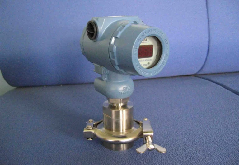
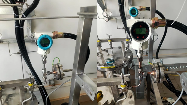
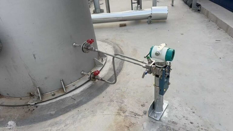
Where The HM60 Fits
HMK’s HM60 explosion-proof pressure transmitter is built around this decision and ships in three variants:
HM60-E
Ex ia ⅡC T5
Intrinsically safe. Needs a barrier; the pick for Zone 0 or live service.
View specs →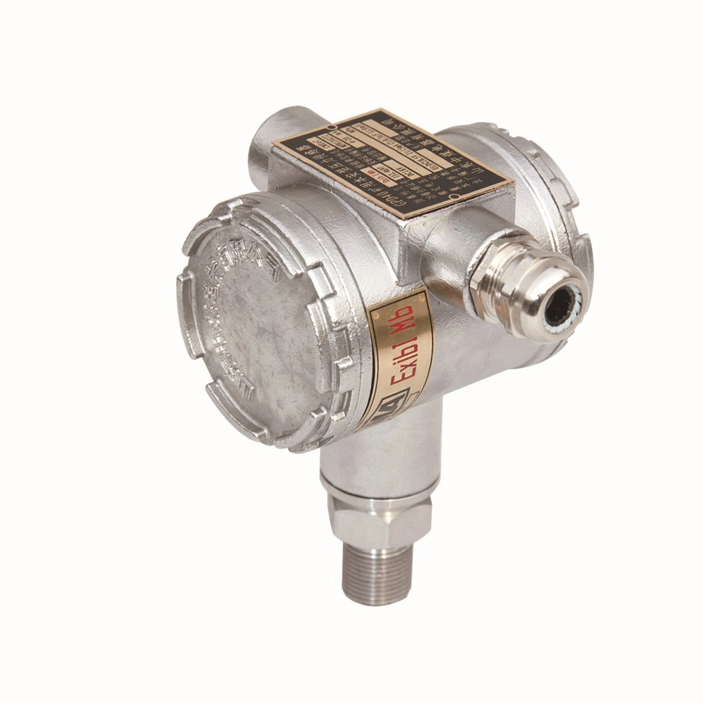
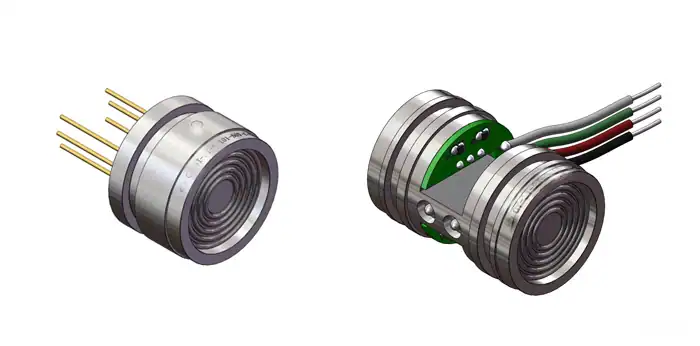
All three share one sensing core: a polysilicon thin-film element welded to a 316 stainless steel port, rated to ±0.1% FS, across -100 kPa to 200 MPa, with 4-20 mA or voltage output on 12-36 VDC. The IIC group clears it for the hydrogen and acetylene groups, not only propane. For a bare sensor, the HE60 explosion-proof pressure sensor shares the family.
One honesty note on certificates: the HM60 holds CNEx explosion-protection certificates and carries the IEC-format marking above. If your project needs ATEX, IECEx, or North American FM/CSA paperwork, confirm the current scope with our engineers first. Browse the range on the pressure transmitters page.
Putting It On The Datasheet
Lock these five selection factors in order, and the part number falls out:
- Read the area classification off the drawing in full, for example Zone 1, IIC or the equivalent Class I, Div 1, Group B.
- For Division 1 or Zone 0/1, choose Ex d or Ex i. Drop to non-incendive only if the area is genuinely Division 2 / Zone 2.
- Set the temperature class from your real process and ambient, not a default.
- Confirm the certificate body your authority accepts (CNEx, ATEX, IECEx, FM, or CSA).
- Send the classification, range, and process conditions to a supplier to confirm the variant. For the HM60, our team will recommend a configuration and quote.
Frequently Asked Questions
Both, by variant. The HM60-E is intrinsically safe (Ex ia ⅡC T5), the HM60-D is flameproof (Ex d ⅡC T6), and the HM60-ED combines them. You pick from your zone and install preference.
No. Non-incendive (Ex nA) protects only in normal operation, so it is limited to Division 2 / Zone 2. Division 1 requires flameproof or intrinsic safety.
Not exactly. Division 1 spans both Zone 0 and Zone 1, because the Division scheme has two gas zones while the IEC scheme has three.
Only with intrinsic safety. An Ex i loop needs a certified barrier plus a cable capacitance and inductance check. A flameproof Ex d unit needs no barrier, but its conduit entries must be sealed.
Add process temperature, ambient, and sensor self-heating to estimate the maximum surface temperature, then pick a class below it and below your gas autoignition point. A 60 °C line usually supports T6; hot-oil service may force T3.
It depends on the location. North America inspects to FM or CSA, most international projects to ATEX or IECEx, and China to CNEx. The protection concept is the same, but the paperwork is not interchangeable, so confirm the right body before you release the tag.
Need a hazardous-area pressure transmitter speced?
Send us your area classification, range, and process conditions and our engineers will recommend the right HM60 variant.
Request a QuoteBrowse Pressure Products