Bourdon Manometer: Working Principle, Types, and Limits
You picked up a spec sheet, or your boss asked you to spec a pressure gauge for a new loop, and now you have to decide whether a Bourdon tube manometer fits the job. We will walk through how the gauge actually works, the three tube shapes you will see, the accuracy classes that show up on every datasheet, the four wetted-part materials worth knowing, and the five field conditions that quietly destroy these gauges. By the end you will know when to spec a Bourdon, and when to switch to a digital transmitter.
What Is a Bourdon Tube Manometer?
A Bourdon tube manometer is a mechanical pressure gauge that uses a curved hollow tube (closed at one end) which straightens slightly under internal pressure; the motion drives a pointer over a calibrated dial. It covers 0.6 bar (~9 psi) up to 7,000 bar (~100,000 psi) and remains the most common mechanical gauge in industrial service.
Quick stats:
- Range: 0.6 bar – 7,000 bar (~9 – 100,000 psi)
- Accuracy: ±0.1% – ±4% FS, classified by EN 837-1 and the equivalent Chinese standard GB/T 1226-2017
- Power and media: no electrical power needed; non-clogging fluids by default, with corrosive media handled by upgrading the wetted-part material; see Which Material for Your Process below
Eugène Bourdon invented this design in 1849 to give steam engineers a safe way to read boiler pressure. Locomotives were exploding in alarming numbers at the time, and the new gauge cut the casualty rate sharply within two years of its introduction. The principle hasn’t changed since. To see all 12 internal components of a typical gauge, read Pressure Gauge Parts.
How a Bourdon Tube Works (Step by Step)
Most pressure-gauge explanations get tangled in beam-bending equations. The mechanism is simpler than that. Five things happen in sequence:
- Process pressure enters the gauge socket.
- The pressure acts on the inside surface of the oval-cross-section tube.
- Because the outer-curve area is larger than the inner-curve area, the net force tries to straighten the tube.
- The closed (free) end of the tube displaces a few millimeters.
- A link, quadrant gear and pinion convert that motion into roughly 270° of pointer rotation on the calibrated dial.
The tube’s spring constant sets the relationship between pressure and dial reading. Calibrate this once, treat the gauge well, and it holds calibration for years. That is why Bourdon gauges are still everywhere despite being 175 years old. No power, no electronics, no firmware. Just a brass or steel tube doing what brass and steel do under load.
C, Spiral, or Helical: Which Bourdon Tube Type for Your Pressure Range
There are three Bourdon tube geometries, each covering a different pressure range:
| Type | Shape | Range | Typical use |
|---|---|---|---|
| C-shape | ~250° arc | ≤ 60 bar (~870 psi) | Industrial standard; covers 80%+ of installations; cheapest option |
| Spiral | Planar coil 2–3 turns | ≤ 25 bar (~360 psi) | Low-pressure precision (deflection larger than C-shape, so resolution is better) |
| Helical | Multi-coil 3D | 60 bar – 7,000 bar (~100,000 psi) | Hydraulic, oil & gas, high-pressure service |
Our quick rule: pick C-shape for any range up to 60 bar; use a helical tube above 60 bar for hydraulic and oil & gas service; use a spiral tube only when sub-10-bar precision needs amplified deflection.
Vendor sanity check: if someone quotes you a spiral for 100 bar service, they are likely substituting because helical stock is short. The spiral will fatigue much faster at that pressure; insist on helical.
The chosen geometry sets the upper pressure limit. The accuracy class (covered next) sets the precision.
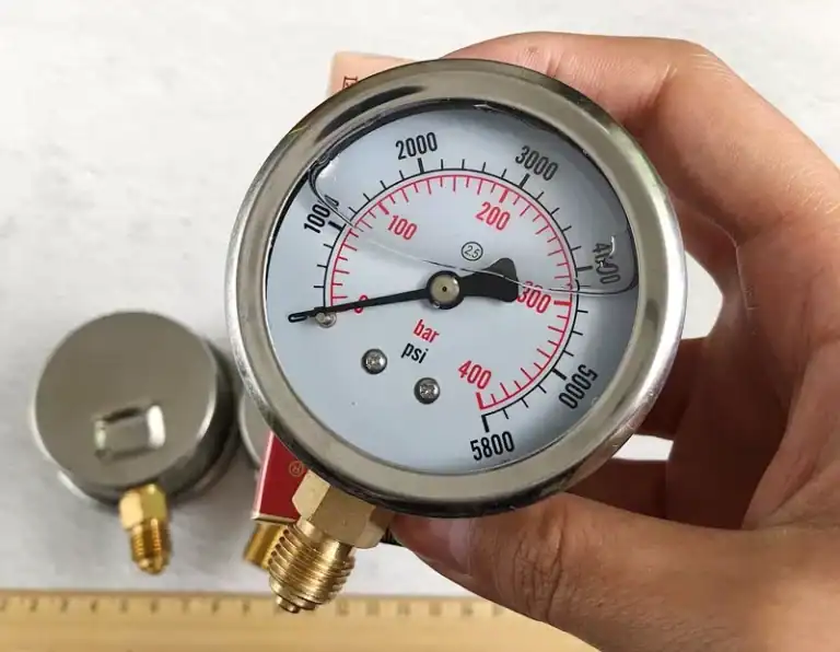
Pressure Range and Accuracy Class: How to Read a Bourdon Spec Sheet
The two numbers you have to read off any Bourdon spec sheet are the full-scale pressure (FS) and the accuracy class. Accuracy class is expressed as ±% of FS, defined identically by EN 837-1 in Europe and GB/T 1226-2017 in China:
| Class | ±% FS | Typical application |
|---|---|---|
| 0.1 | 0.1% | Master / reference gauges, primary calibration |
| 0.25 | 0.25% | Test gauges, transfer-standard work |
| 0.5 | 0.5% | High-spec process control |
| 1.0 | 1.0% | General process gauges |
| 1.6 | 1.6% | Industrial standard, most-shipped grade |
| 2.5 | 2.5% | Utility / HVAC monitoring |
| 4.0 | 4.0% | Indication only, low-stakes service |
The 75% rule: keep your operating reading inside 25%–75% of full scale. Below 25% the accuracy band swallows your signal; above 75% you accelerate fatigue and risk overpressure damage.
A “Class 1.6” gauge stamped to either standard meets the same ±1.6% FS specification, so a European EN 837-1 unit and a Chinese GB/T 1226 unit are interchangeable from an accuracy standpoint. For class-vs-reading guidance and how the accuracy band shifts across the dial, see How to Read a Pressure Gauge.
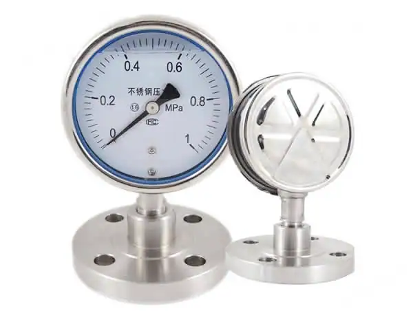
Which Material for Your Process: Bronze, 316L, Monel, or Inconel
Most Bourdon failures we see in the field aren’t about pressure; they’re about the wrong wetted-part material against the process fluid. Here is the lookup table our application engineers actually use:
| Process fluid | Recommended material | Limits / notes |
|---|---|---|
| Air, water, low-temperature steam | Phosphor-bronze | Up to 60 bar, lowest-cost general-purpose option |
| General industrial / mild chemical | 316L stainless | Up to 70 bar in C-shape; switch to helical above 70 bar; for oxygen service use oil-free cleaned 316L per ASTM G93 |
| Seawater, hydrofluoric acid, ammonia, reducing acids | Monel 400 | Resists chloride and reducing environments; never use copper alloys with ammonia |
| High-temperature H₂S or chlorine (sour service) | Inconel 600 / 625 | Compliant with NACE MR0175 for sour-service applications |
Two rules of thumb that cover most edge cases: never specify copper or brass with ammonia (the gauge will fail in months), and never use plain 316L on chloride-rich seawater above 60 °C unless you accept replacing it on a 12-month schedule.
Five Limits That Kill a Bourdon Gauge
A Bourdon gauge fails predictably in five ways: overpressure, vibration, pulsation, temperature drift, and metal fatigue. Each has a quantifiable threshold and a field fix.
- Overpressure (> 1.3× FS). The tube takes a permanent set; the zero point shifts up by 5–20%. Fix: install an over-range stop pin inside the gauge, or an upstream pressure-relief valve. Per the Chinese verification regulation JJG 52, the gauge should show no residual offset after a 1.25× FS hold during certification.
- Vibration (sustained > 1g RMS at 10–500 Hz). The pointer flutters, gears and pivots wear, and the dial face slowly drifts off its mounting. Fix: switch to a glycerin-filled case, or use a remote diaphragm-seal mount with a capillary line.
- Pulsation (cyclic ±10% FS amplitude at >2 Hz). Reading becomes unreadable, and fatigue accumulates faster. Fix: install a snubber, pulsation orifice, or pulse-damping needle valve at the gauge inlet.
- Temperature drift (≈ 2% per 30 °C above the 23 °C reference). The whole error band shifts. Fix: use a diaphragm seal with capillary line, or relocate the gauge to a thermally stable zone.
- Fatigue (~10⁶ pressure cycles). Hysteresis grows and the zero shifts. Fix: schedule periodic recalibration per JJG 52, with intervals typically annual for a Class 1.6 gauge in process service, and every six months for cyclic-pressure applications.
Most field failures we get called on are combinations: a vibrating pump base plus a partly clogged snubber will kill a Class 1.6 gauge inside a year.
When to Use Bourdon vs U-tube vs Digital Transmitter
Our honest decision framework:
Stay with Bourdon when you only need local visual indication, no remote monitoring, no electrical power is available at the install location, you are in a hazardous area without an intrinsically safe barrier, or you just need a sanity-check gauge on a small pressure vessel.
Migrate to a digital transmitter when any of these three conditions apply:
- You need remote or SCADA monitoring → 4–20 mA or HART signal becomes mandatory
- You need closed-loop control → sub-second response and analog/digital output
- You need data logging or predictive maintenance → digital protocol such as HART, FOUNDATION Fieldbus, or PROFIBUS
Use a U-tube manometer only for calibration reference, very low differential pressure (<1 bar), lab work, or teaching demonstrations.
| Dimension | U-tube | Bourdon | Digital transmitter |
|---|---|---|---|
| Principle | Liquid column balance | Elastic tube deformation | Strain / capacitive / MEMS |
| Range | <1 bar | 0.6 – 7,000 bar | 0 – 10,000 bar |
| Accuracy | ±0.1 – 0.5% FS | ±0.1 – 4% FS | ±0.025 – 0.5% FS |
| Output | Visual | Visual | 4–20 mA / HART |
| Remote / Power | ✗ / ✗ | ✗ / ✗ | ✓ / ✓ |
For a deeper transmitter primer, see Pressure Transmitter Types, Pressure Sensor vs Transducer vs Transmitter, and HART vs 4-20mA.
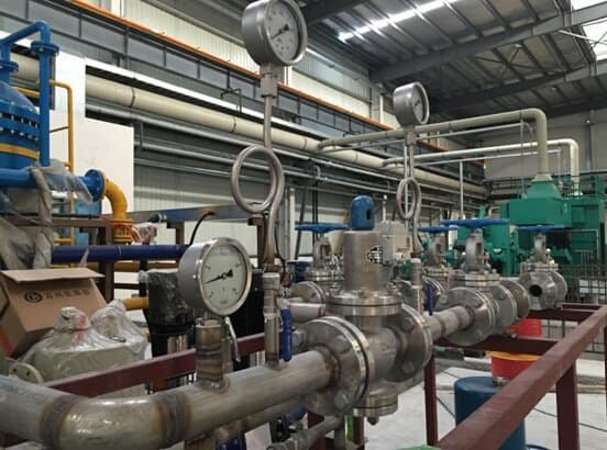
Industrial Applications: Where Bourdon Still Wins
Despite the migration to digital transmitters, four industries still spec Bourdon as the default:
- Hydraulic systems (presses, injection molders): C-shape, 0–25 MPa range, glycerin-filled case. Vibration handling is mandatory here.
- Steam and utility piping (refineries, paper mills, boilers): C-shape in 316L with a siphon (pigtail) and isolation valve; the siphon protects against condensate cycling.
- Refrigeration and HVAC: compound gauge from -1 to 25 bar; the wetted-part material must avoid copper alloys when ammonia is the refrigerant.
- Oil & gas / sour service: helical Monel 400 or Inconel 625, compliant with NACE MR0175.
Field example: on a 1,000-ton hydraulic press at a Tier-1 automotive supplier, sustained ±15% pointer flutter on the 0–25 MPa gauge usually traces to a stuck pressure-relief valve, not the gauge itself. Cross-check with a master gauge before condemning the Bourdon.
Frequently Asked Questions
Does a Bourdon gauge measure absolute or gauge pressure?
Gauge pressure by default. An absolute version exists with a sealed, evacuated reference chamber. For the difference between absolute and gauge pressure, see Absolute Pressure vs Gauge Pressure.
Can a Bourdon gauge measure vacuum?
Yes; a compound Bourdon gauge reads from -1 bar (full vacuum) up through a positive range. See How to Read a Vacuum Gauge.
What is the difference between a Bourdon manometer and a U-tube manometer?
A Bourdon uses elastic deformation of a curved tube and covers 0.6 bar to 7,000 bar. A U-tube uses liquid-column balance and is limited to low differential pressures (<1 bar). The Bourdon gives mechanical amplification into a dial reading; the U-tube is a direct hydrostatic measurement with no moving parts.
What are the disadvantages of a Bourdon tube?
Five repeatable failure modes (overpressure, vibration, pulsation, temperature drift, and metal fatigue), all covered with quantified thresholds in the Five Limits section above.
How do I check if my Bourdon gauge is still accurate?
Three options, in increasing rigor. In the field with no reference, compare the dial reading against a co-located 4-20 mA transmitter on the same line; agreement within the gauge’s class tolerance is a passing sanity check. In the workshop, compare against a master gauge of class 0.1. For full traceability, run the gauge on a deadweight tester at 25, 50, 75, and 100 percent of full scale per JJG 52 or EN 837-2. For class-vs-reading interpretation, see How to Read a Pressure Gauge.
Related field guide: when a Bourdon dial bounces during operation rather than holding steady, the five-cause troubleshooting tree for a fluctuating oil pressure gauge isolates whether the fault is mechanical, hydraulic, or in the loop.
The compound gauge variant of the Bourdon principle is the field standard for refrigeration manifold sets and other applications that need both vacuum and positive readings on one dial. For typical low-side readings by refrigerant (R-22 / R-410A / R-32 / R-134a / R-404A) and other negative-pressure applications across industries, see Negative Pressure Gauge Applications.
For the accuracy class breakdown that applies to Bourdon-tube gauges (Cl 1.0 / 1.6 / 2.5 standard industrial; Cl 0.4 or finer for test gauges), see Pressure Gauge Accuracy Class.
Next step: Need help picking the right pressure transmitter or upgrading from a mechanical gauge? Send your spec sheet for a model recommendation in 24 h. Get in touch →