NPT vs BSP/G Thread: Pressure Connection Selection Guide
Picking the wrong thread for a pressure gauge or transmitter port turns a simple connection into a leak. NPT and G (BSPP) look similar at first glance, but they do not share a sealing principle, a thread angle, or a pitch. The two were designed in different countries against different standards, and forcing one into the other under pressure cycling is a common field failure. This guide walks through the differences so a spec writer or drafter can pick the correct port the first time, and verify it before fittings get torqued in place.
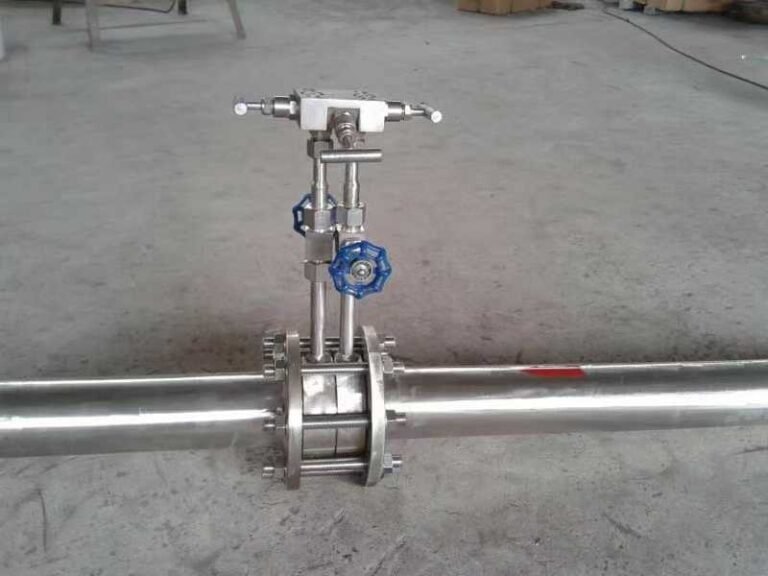
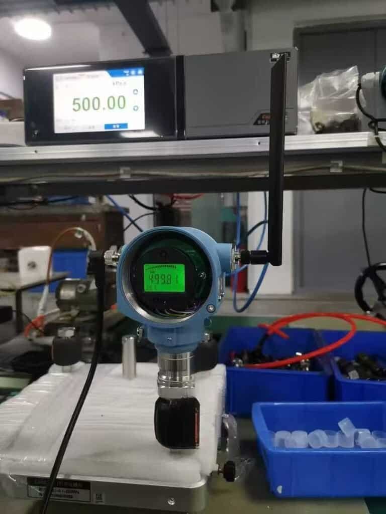
The thread is just one of twelve cooperating parts inside a pressure gauge — the socket is what connects the rest of the assembly to your process line.
NPT vs G Thread: The Quick Compatibility Answer
NPT and G are not compatible. NPT is a tapered American pipe thread that seals on the flanks of the threads themselves, with sealant tape or a paste filling the helical leak path. G is a parallel British pipe thread that does not seal on the threads at all — it relies on a bonded washer, an O-ring on the boss, or a flat-face gasket on the fitting shoulder. The thread angles also differ: NPT cuts at 60 degrees and G cuts at 55 degrees, so even when an outer diameter looks close, the flanks never meet cleanly.
A 1/4 NPT male will start into a G 1/4 female and feel like it is going in. After two or three turns it will jam against mismatched flanks and tilt off-axis. Under steady pressure it may hold for a shift; under cycled pressure or vibration it leaks. Treat NPT and G as different ports, not as variants of the same thread.
Side-by-Side: Geometry, Angle, Pitch, Sealing
The fastest way to see why mixing the two fails is to put them next to each other.
| Property | NPT (American) | G / BSPP (British parallel) |
|---|---|---|
| Form | Tapered 1:16 (about 1.79 degrees per side) | Parallel (no taper) |
| Thread angle | 60 degrees | 55 degrees |
| Crest / root | Flat crest, flat root | Rounded crest, rounded root |
| Sealing surface | Thread flanks themselves | Boss face + bonded washer or O-ring |
| Pitch (1/4 size) | 18 TPI (1.411 mm pitch) | 19 TPI (1.337 mm pitch) |
| Pitch (1/2 size) | 14 TPI (1.814 mm pitch) | 14 TPI (1.814 mm pitch) |
| Sealant required | Yes — PTFE tape or thread paste | No on the threads; gasket or O-ring on the face |
| Re-use cycles | Limited; tape gets damaged on each disassembly | High; gasket replaces in seconds |
Two takeaways from the table: the 60 vs 55 degree angle gap means flanks cannot mate even when the diameter is right, and the sealing strategy is different in kind, not in degree. NPT relies on plastic deformation of the metal under torque to close the helix; G keeps the threads loose and seals somewhere else. You cannot get a tight, stable joint by mixing the two regardless of how much sealant tape you wrap.
Standards Behind Each: ASME B1.20.1, ISO 228-1, JIS B0203, GB/T 7306/7307/12716
Most online guides skip the standards layer. For a spec writer it is the most important paragraph in the article, because every drawing call-out, every QA inspection, and every customs declaration ties back to one of these.
| Region | Standard | Thread it covers | Notes |
|---|---|---|---|
| United States | ANSI/ASME B1.20.1 — Pipe Threads, General Purpose (Inch) | NPT (tapered, 60°, sealing on threads) | The reference document for any NPT call-out in North America |
| International (parallel) | ISO 228-1 — Pipe threads where pressure-tight joints are not made on the threads | G / BSPP (parallel, 55°) | Used widely across Europe, the UK, and exported instrumentation in EMEA |
| International (tapered) | ISO 7-1 — Pipe threads where pressure-tight joints are made on the threads | R / Rc / Rp (BSPT, 55° tapered) | Adjacent family to G; not the same as NPT despite both being tapered |
| Japan | JIS B0203 (tapered, PT), JIS B0202 (parallel, PF / PG) | PT and PF — historic Japanese pipe threads, similar to BSPT and BSPP | Still common on legacy Japanese equipment |
| China | GB/T 7307 — 55° non-sealed parallel pipe thread; GB/T 7306 — 55° sealed tapered pipe thread; GB/T 12716 — 60° sealed pipe thread | GB/T 7307 maps to G / BSPP (ISO 228-1); GB/T 7306 maps to R / BSPT (ISO 7-1); GB/T 12716 maps to NPT (ASME B1.20.1) | All three commonly co-cited on Chinese instrument drawings |
For an export-grade pressure transmitter sold into multiple regions, the practical move is to specify the connection by the international standard it satisfies (ISO 228-1, ISO 7-1, ASME B1.20.1) and let the regional drawing notation track that. GB/T 7307, GB/T 7306, and GB/T 12716 are the formal Chinese hooks if the project sits inside a GB-compliant procurement chain.
Why You Cannot Mix the Two (and what fails first)
The first thing to fail is the seal, not the thread itself. A 1/4 NPT male torqued into a G 1/4 female will engage the first one or two threads at the small-diameter end of the taper, then bind on the 5-degree angle mismatch. The metal-to-metal contact is intermittent — one flank contacts, the other has a gap. Tape or paste plugs the obvious gap on the first install, but it gets extruded under pressure cycling and then the joint weeps.
A second failure mode is the boss face on the female side. G ports are designed for a sealing washer or an O-ring at the face. NPT female ports usually do not provide a flat sealing land at the entry. Even if the threads do hold, a G male in an NPT female has nothing to seal against on the face. The result is a slow leak that only shows up when the system holds pressure overnight.
Vibration is the third failure path. The flat crest and root of NPT threads make the joint relatively stiff once torqued. The rounded crest and root of G threads, combined with parallel geometry, give some elastic compliance — fine in their own port, but unstable in a tapered NPT counterpart. Field experience commonly cites this as a contributor to nuisance pressure transmitter leaks at instrument tubing transitions, especially on long-running plants where the original port spec was not enforced.
The bottom line: the joint may hold for a leak test, hold for a shift, or hold for a week. It does not hold for the design life of a pressure instrument. Plan the port match at design time.
Where Each Is Used: Region and Industry
NPT dominates North America. Any pressure gauge, transmitter, valve, or pipe fitting purchased in the United States, Canada, and most of Mexico defaults to NPT unless specified otherwise. The exceptions are aerospace, automotive (which often specify SAE straight thread), and specialty cryogenic or sanitary services.
G / BSPP dominates the UK, most of Europe, and large parts of Asia outside Japan. Continental European instrument makers ship G ports as standard for industrial pressure measurement, often paired with a copper or composite sealing washer. UK process plants and most Indian, Australian, and Southeast Asian projects follow the same convention.
Japan straddles the line. Legacy plants run on PT (BSPT-equivalent) and PF (BSPP-equivalent) per JIS B0203 and B0202. Newer Japanese equipment, especially for export, often switches to G or NPT depending on the destination market.
China runs both. Domestic process plants commonly specify GB/T 7307 (55° parallel, BSPP-equivalent) and GB/T 7306 (55° tapered, BSPT-equivalent) on industrial equipment, and GB/T 12716 (60° sealed, NPT-equivalent) on systems sourced from US-spec processes. Sinopec and CNPC project specifications often call out the matching ISO or ASME standard alongside the GB number to keep dual-source procurement open.
A practical rule: if the project document references ASME or ANSI, default to NPT. If it references ISO, BS EN, or DIN, default to G. If it references GB, check whether GB/T 7307 (55° parallel), GB/T 7306 (55° tapered), or GB/T 12716 (60° NPT-style) is invoked.
How to Identify a Thread on an Existing Fitting (3-Step Method)
Most field engineers have a fitting in hand and need to know what it is before ordering a replacement. The 3-step method below works without a thread micrometer.
Step 1 — Visual taper check. Look at the fitting from the side. If the diameter narrows visibly from the open end inward over a few threads, it is tapered (NPT, BSPT/R, PT, GB/T 7306). If it stays parallel, it is straight (G/BSPP, PF, ISO 228-1). A straightedge laid against the threads makes this obvious.
Step 2 — Pitch gauge. Press a thread pitch gauge against the threads until the gauge teeth seat fully into the valleys with no gap. The gauge reading is your TPI (US) or pitch in mm (metric). For 1/2-size threads NPT and G both run 14 TPI, so pitch alone is not always conclusive — combine with steps 1 and 3.
Step 3 — Angle gauge. A 60° flank gauge will mate cleanly with NPT; a 55° flank gauge mates with G/BSPP. If you do not have an angle gauge, the secondary signal is crest shape: NPT crests are flat-cut; G crests are subtly rounded.
A separate quick check on a male fitting: try threading it into a known-good female of each type, finger-tight only. If it bottoms out cleanly within a few turns and tightens uniformly, the female is the same family. If it binds, tilts, or stops short, the families are different.
NPT to G/BSPP Size Equivalence Table
This is the table most spec writers actually need. Each size pair is the closest dimensional cousin — not interchangeable, just adjacent for adapter selection.
| Nominal size | NPT OD (mm) | NPT TPI | G / BSPP OD (mm) | G TPI | Equivalent? |
|---|---|---|---|---|---|
| 1/8 | 10.24 | 27 | 9.728 | 28 | Adapter required |
| 1/4 | 13.71 | 18 | 13.157 | 19 | Adapter required |
| 3/8 | 17.27 | 18 | 16.662 | 19 | Adapter required |
| 1/2 | 21.34 | 14 | 20.955 | 14 | Adapter required (closest pair) |
| 3/4 | 26.67 | 14 | 26.441 | 14 | Adapter required (closest pair) |
| 1 | 33.40 | 11.5 | 33.249 | 11 | Adapter required |
| 1-1/2 | 48.26 | 11.5 | 47.803 | 11 | Adapter required |
| 2 | 60.32 | 11.5 | 59.614 | 11 | Adapter required |
Outer diameters are within fractions of a millimeter for most sizes, which is exactly why the two get mixed up. The thread angle and the sealing principle make them incompatible regardless.
HMK Pressure Instrument Port Options
For pressure transmitters and gauges shipped from HMK, the standard port options cover both worlds. Specify at order time; mid-life conversion in the field requires a sealing adapter and is rarely as clean as ordering the right port.
| HMK series | Standard process connections | Other thread options | Notes |
|---|---|---|---|
| HM30 Micro DP transmitter | M20×1.5 (F1), G 1/4 (F2), Φ8 barb with M10×1 (F3) | Custom (F0) for NPT or specialized threads | HVAC pressurization and cleanroom service typically uses G 1/4 |
| HM27 vacuum / absolute | M20×1.5, G 1/4, sanitary clamp | NPT available on request | Vacuum service prefers G with face O-ring for repeatable seal |
| HM41 compact pressure switch | M20×1.5 (F1), G 1/4 (F2) | Custom (F0) for NPT or other threads | Switch + display in one head; relay output via NO/NC contacts |
A guiding principle: pick the port that matches the existing process tubing in the plant, not the cheapest available option. A multi-instrument project that ships with mixed NPT and G ports tends to lose the cost saving back in commissioning rework.
Adapters and Conversion: Practical Guidance
Adapters are common but they are not free. A NPT-to-G adapter adds one extra leak path, one extra wrench torque step, and one extra spare-parts SKU. For a single retrofit, that is acceptable. For a 100-instrument pressure tubing rebuild, ordering the right port from the factory is faster and tighter.
Where an adapter does make sense:
- One-off field replacement when the old instrument was the wrong port and needs to be swapped same-day
- Test-bench setups where multiple thread types arrive on the same rig
- Cross-region service spares where holding both port options for every SKU is uneconomical
When specifying an adapter, match the standard on each end to its sealing principle: an NPT end uses tape or paste, a G end uses a bonded seal washer. Mixing sealants — for example tape on a G port — produces a joint that looks tight at install and weeps within days under cycled pressure.
Related reading: How to Read a Pressure Gauge Correctly Every Time — analog dial basics, dual-scale traps, tell-tale needles, and 5-step calibration check from the field.
FAQ
Are NPT and G threads compatible?
No. The thread angles (60° vs 55°), the form (tapered vs parallel), and the sealing principle (tape on flanks vs O-ring on face) are all different. They cannot share a port reliably under cycled pressure.
Is G the same as NPT?
No. G refers to ISO 228-1 parallel pipe threads with a 55° angle; NPT is ASME B1.20.1 tapered pipe threads with a 60° angle. The closest tapered relative to NPT in the British family is R (BSPT, ISO 7-1), but R is also 55° and still not the same as NPT.
Is G1/4 the same as 1/4 NPT?
No. G 1/4 is parallel, 19 TPI, 13.157 mm OD, sealed at the face. 1/4 NPT is tapered 1:16, 18 TPI, 13.71 mm OD, sealed on the threads. The dimensional similarity is what causes confusion in the field.
What is the G thread equal to?
G is equivalent to BSPP (British Standard Pipe Parallel) and is defined by ISO 228-1. It is also dimensionally equivalent to JIS PF (parallel) and to GB/T 7307 (China parallel pipe thread).
Can I use PTFE tape to seal a G thread joint?
No. G thread joints seal on a face gasket or O-ring, not on the threads. PTFE tape on a G thread is a sign the assembler treated it like an NPT joint and the joint will likely weep under cycled pressure.
How do I specify the right port for a multi-region instrument fleet?
Specify by the relevant standard (ASME B1.20.1, ISO 228-1, ISO 7-1, JIS B0203, or the matching GB number) and pair the port with the regional process tubing standard. For an HMK pressure transmitter shipped into both NA and EU plants, ordering NPT for the NA portion and G for the EU portion at the factory is cheaper than retrofitting adapters in the field.
Related reading: The 1/8 NPT thread is also the standard automotive sender port; if you are speccing an electric oil gauge, see our electric oil pressure gauge guide.
Next step: Compare HMK pressure instruments by category. Get in touch →
Related reading: After thread selection, the next step is matching the transducer to your industry. See pressure transducer applications by industry.