How Differential Pressure Flow Measurement Works
Differential pressure flow measurement infers flow rate from the pressure drop across a known restriction in the pipe. Bernoulli’s principle says velocity rises when pressure falls across the restriction, so a calibrated obstruction plus a DP transmitter gives you flow. The technique sits inside refineries, gas custody stations, and large-bore steam headers because the physics is simple and the parts are field-rebuildable.
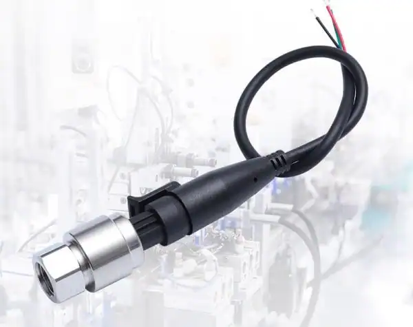
A common pairing for flow elements is the HM31 differential pressure transmitter.
Related guide: For the air-side selection on HVAC duct and filter points — range, switch vs transmitter, and 4-20 mA output are covered in choosing an HVAC differential pressure transmitter. For applying the same square-law in reverse to judge filter loading, see filter differential pressure monitoring.
This guide is for the process or instrumentation engineer just told to specify a flow meter for a new line. You want enough depth to defend the choice in design review. If you already know the basics of a DP transmitter working principle, this is the layer above — how the transmitter pairs with a primary element to read flow.
DP flow remains the workhorse for steam and gas custody transfer. The math is well-understood, and primary elements rebuild on a Saturday shift. It loses to Coriolis or magnetic flow when the fluid is dirty, when the Reynolds number drops, or when the spec demands accuracy below ±0.5% without on-site proving. For sub-atmospheric process measurements that look like flow problems but are not, see the vacuum gauge guide.
The Bernoulli Physics in 60 Seconds
Energy stays constant along a flowing pipe. When the pipe area shrinks at a primary element, velocity rises to push the same mass through a smaller cross-section. Static pressure falls by the same kinetic-energy difference. Measure that pressure drop and you have measured velocity — which means you have measured flow.
The working equation for an incompressible fluid through a sharp restriction is Q = K · A · √(2 · ΔP / ρ), where K is a discharge coefficient set by the geometry, A is the throat area, and ρ is the fluid density. The square root is the part you cannot ignore: doubling the flow rate quadruples the differential pressure. That fact drives every decision in the rest of this guide.
You can run this relationship both ways with our DP flow calculator — it converts a differential-pressure reading into flow rate through the square root, and lays out the percent-DP to percent-flow that trips people up.
A worked number: water at 20 °C in a DN100 line through a beta-0.55 orifice plate. Density 998 kg/m³, ΔP measured at 25 kPa, discharge coefficient C = 0.6 from ISO 5167 flange-tap tables. Throat area A = π·(0.055/2)² = 2.376×10⁻³ m². Q = (C·A / √(1−β⁴)) · √(2·ΔP/ρ) = (0.6·2.376×10⁻³ / 0.953) · √(50.1) ≈ 0.0106 m³/s ≈ 38 m³/h. Sanity check the math before you trust the field reading.
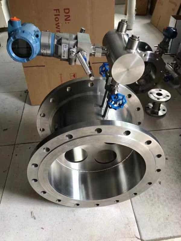
The Two-Element Architecture
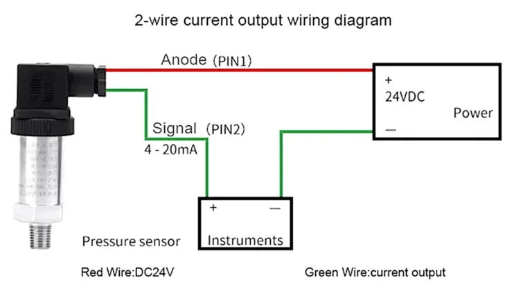
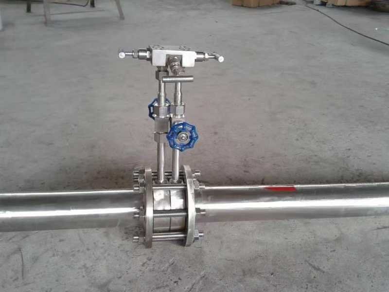
A DP flow loop has two elements that fail and calibrate independently. The primary element is the mechanical restriction in the pipe — orifice plate, venturi, V-cone, wedge, flow nozzle, Pitot tube. It creates the differential. The secondary element is a DP transmitter that converts the pressure drop into a 4-20 mA signal.
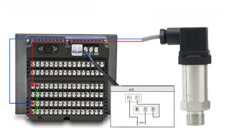
Two impulse lines run from the high and low pressure taps through a 5-valve manifold into the transmitter. The manifold isolates and equalizes for safe maintenance. The 4-20 mA output then carries the signal back to the DCS, with 4-20 mA loop wiring following the same rules that govern any pressure loop.
Treat the two elements separately when you spec, install, and calibrate. Replacing an orifice plate has nothing to do with re-zeroing the transmitter.
Primary Element Types
Six primary elements cover almost every industrial DP flow application:
- Orifice plate. Sharp-edged hole in a flat plate. Cheapest and most documented, but needs the longest upstream straight run — 30 D before a beta-0.7 plate without a flow conditioner.
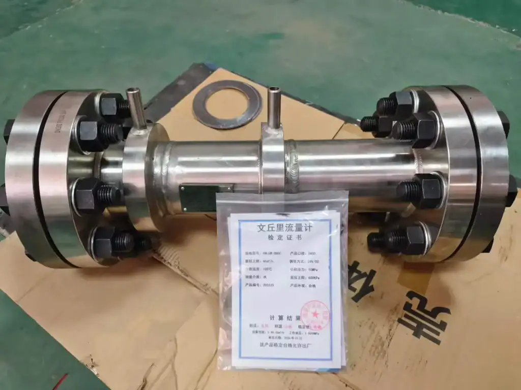
- Venturi tube. Smooth converging-diverging nozzle. Permanent pressure loss is one-third of an orifice at the same beta. Pick it when pumping cost matters more than CapEx.
- V-cone. A cone hung in the pipe centerline conditions the flow profile itself. Field reports from Sinopec natural gas custody stations show V-cone retrofits reducing upstream straight-pipe requirements from 30 D on the old orifice to roughly 3 D, with measurement repeatability moving from ±1.0% to ±0.5%.
- Wedge meter. Wedge-shaped restriction. Best with slurry and viscous fluids — Asian fertilizer plants use it for ammonium phosphate.
- Flow nozzle. Short contoured restriction. Higher discharge coefficient than an orifice and tougher under high-velocity steam.
- Pitot / averaging Pitot. Insertion devices. Lowest pressure loss, lowest accuracy, common on retrofit duct flow.
DP Transmitter Specs That Matter
The primary element creates the differential. The DP transmitter has to read it accurately across the full flow range, survive the static line pressure, and tell the DCS when something is wrong. Spec sheets cluster around five attributes that determine whether the loop holds its accuracy target into year two.
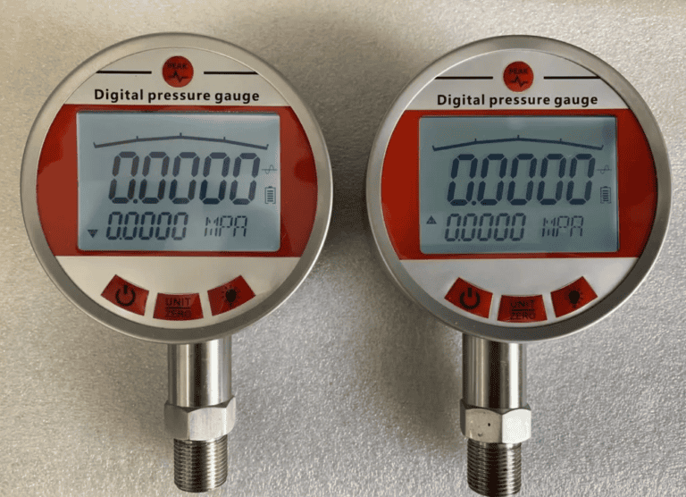
Sensing technology. Three diaphragm types dominate modern DP transmitters. Capacitive sensors lead on accuracy and zero-point stability — the diaphragm forms one plate of a capacitor and the readout carries almost no noise. Piezoresistive silicon costs less and tolerates higher temperatures, but it drifts more over a decade. Sapphire-on-silicon survives in hydrofluoric and concentrated acid lines where the other two corrode. HMK’s HM33 series uses capacitive cells; HM34 uses diffused-silicon piezoresistive for general process duty.
Accuracy class and turn-down. Demand ±0.075% of span at full turn-down, not ±0.075% of reading at 1:1. A 100:1 turn-down on the spec sheet usually drops to 10:1 once you hold the same accuracy class — the static-pressure and temperature corrections eat into the budget. For DP flow, 5:1 turn-down with ±0.5% is realistic; 10:1 with ±0.5% needs a top-tier transmitter.
Static-pressure rating. A DP transmitter sees the line pressure on both sides. A 4 kPa span on a 4 MPa line means the static pressure is 1,000 times the working differential. The static-pressure URL effect — typically 0.05% of URL per 7 MPa — has to be accounted for in the calibration math, not ignored.
Digital diagnostics. HART 7 or Foundation Fieldbus output unlocks self-diagnostics: plugged-impulse-line detection, partial-blockage alarms, and trend logs the DCS can graph. On any custody loop, that capability pays for itself the first time it catches a frozen impulse line before the operator does. For flow points too remote or scattered to wire back, a wireless DP transmitter for remote flow points trends the same reading without a cable run.
Worked calculation. A line at 1.6 MPa static, design flow 200 m³/h water through a beta-0.7 orifice DN150, expected differential 50 kPa. Pick a 0–100 kPa transmitter with ±0.075% span and HART. The static-pressure URL contribution at 1.6 MPa is roughly 0.011% of URL — adding the static-pressure error to the base accuracy by RSS (root sum square) gives ±0.076%, well inside the ±0.5% loop budget.
Picking the Right Primary Element
Match the primary element to the constraint that matters most:
| Element | Best when | Avoid when |
|---|---|---|
| Orifice plate | Clean liquid or gas, plenty of straight pipe | Dirty fluid, short runs, pumping cost critical |
| Venturi tube | Clean fluid, pumping cost matters | Tight budget, retrofit space limited |
| V-cone | Short straight runs, mixed-phase, custody | Very clean long pipes — paying for unused capability |
| Wedge meter | Slurry, viscous, abrasive | Ultra-clean services where wake adds noise |
| Flow nozzle | High-velocity steam, high temperature | Liquid services with available orifice budget |
| Pitot / averaging | Retrofit ducts, low pressure loss | Custody transfer, dirty gas |
GB/T 2624-2006 adopts ISO 5167 with stricter pressure-tap rules in the beta = 0.20 to 0.75 range. Chinese refineries default to flange taps. If you are sourcing from or exporting to China, confirm which tap arrangement the discharge coefficient was derived for — mixing an ISO 5167 corner-tap coefficient with a flange-tap installation bakes in a 1 to 2 percent error.
When DP Flow Beats Other Technologies — and When It Loses
DP flow is not the right answer for every line. The matrix below covers the comparison most engineers actually run:
| Technology | Best fit | Typical accuracy | DP wins? |
|---|---|---|---|
| DP (orifice / venturi / V-cone) | Steam, gas custody, large-bore liquid | ±0.5–1.0% | Wins on cost and custody acceptance |
| Coriolis | Mass flow on viscous or unknown-density liquids | ±0.1% | Loses on capital cost, large-pipe penalty |
| Vortex | Steam and clean gas, mid-range pipes | ±1.0% | Comparable for steam; DP scales bigger |
| Magnetic | Conductive liquids only | ±0.5% | DP loses; mag wins |
| Ultrasonic | Clean liquid, retrofit, large pipes | ±1–2% | Comparable; ultrasonic better on pumping cost |
DP flow wins on four conditions: steam or natural gas at custody-transfer scale, pipe larger than 6 inches, maintenance crews who rebuild primary elements in-house, and specs that call for AGA-3 traceability. It loses when the fluid is dirty, when Reynolds drops below 10,000, or when the contract demands ±0.1% without sending the meter to a lab. For sub-atmospheric service, an absolute pressure reference usually wins instead.
The Square-Root Problem and Turndown Reality
Because ΔP scales with the square of flow, a meter sized for full flow at 100 kPa differential reads only 1 kPa at 10% flow. Sensor noise that was invisible at high flow becomes 25 percent of reading at low flow. That is why a standard DP flow loop turns down only 3:1 to 5:1 in practice, against 100:1 for a Coriolis or 50:1 for a precision vortex.
The square-root extraction has to happen somewhere — and where you put it changes how noisy the low-flow signal looks. The classic location is inside the DP transmitter, which outputs a linearized 4-20 mA already in flow units. Field practice on PetroChina and Sinopec refining projects often moves the extraction to the DCS instead, leaving the transmitter linear in pressure. Engineers do this because keeping the raw differential available makes plugged-impulse-line diagnostics work, and the DCS can dampen low-flow noise more aggressively than the transmitter firmware does. Multiple gongkong.com threads document the practice, though no English-language vendor manual covers it.
Installation Gotchas That Ruin Accuracy
Bad installation kills more DP loops than bad transmitters do. The four rules that matter:
- Upstream straight run. Standard sizing assumes 10 D upstream and 5 D downstream as a minimum. Without a flow conditioner, an orifice plate at beta 0.7 wants 30 D after a single elbow.
- Impulse line geometry. Both lines have to slope the same direction at the same angle. Trapped air on one side and liquid on the other create a static offset that reads as phantom flow.
- Valve manifold sequence. Always equalize before opening either isolation valve. Reversing the order pressurizes the low side against an empty high side and flips the diaphragm.
- Winter freezing protection. Refineries in northeast China below -35 °C protect impulse lines with three layers: electric heat tracing on a thermostat, a 50 percent ethylene glycol fill, and a flanged insulation enclosure. SH 3501-2011 specifies the triple protection.
Standards and Calibration
ISO 5167 is the international DP flow standard. AGA Report No. 3 governs natural gas custody transfer in North America. GB/T 2624-2006 is the matching Chinese national standard, technically equivalent to ISO 5167 with stricter pressure-tap rules.
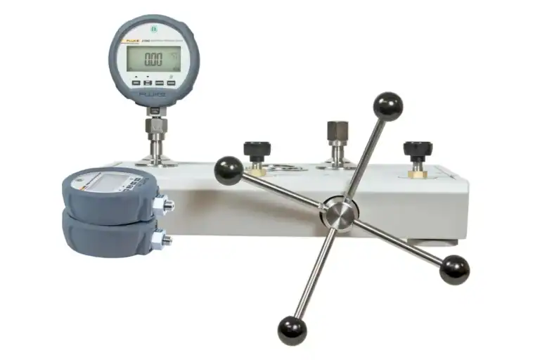
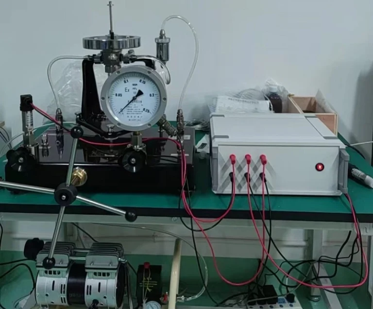
JJG 640-2016 is the Chinese metrology verification regulation for DP flow meters. It mandates four checks once per year on every transmitter in custody-grade service: zero-point, range-span, static-pressure effect, and temperature drift. Field practice in non-custody refining and petrochemical sites is two-year intervals on the secondary element, with primary-element inspection at every shutdown. For traceability, ISO 17025 covers the lab framework. A live calibration on a HART-capable transmitter follows the same procedure as any DP transmitter calibration.
Three Steps Before Your Next Flow Meter Spec
Before signing the next flow-meter purchase order:
- Write the operating window on one line — design flow, minimum flow, fluid, temperature, pipe size, static line pressure.
- Pick the primary element from the matrix above; pick the DP transmitter from the five specs in this guide.
- Compare the loop against Coriolis, vortex, mag, and ultrasonic on accuracy, pumping cost, and turn-down. If DP wins, build it.
The HMK differential pressure transmitter family covers HM33, HM34, and the 1151 series. Pair it with the right primary element and the loop will outlast the project.