CYG411 — Free-Field Dynamic Pressure Sensor
CYG411 Free-Field Pressure Sensor: Outdoor Blast Wave Measurement
Slim Φ6.5×406 mm teardrop probe for low-distortion wavefront capture in outdoor explosive shock-wave testing. 1 to 10 MPa range, 180-360 kHz natural frequency, 1 µs rise time. Cavity-less flush diaphragm. Anti-IR optical option for near-field detonation environments.
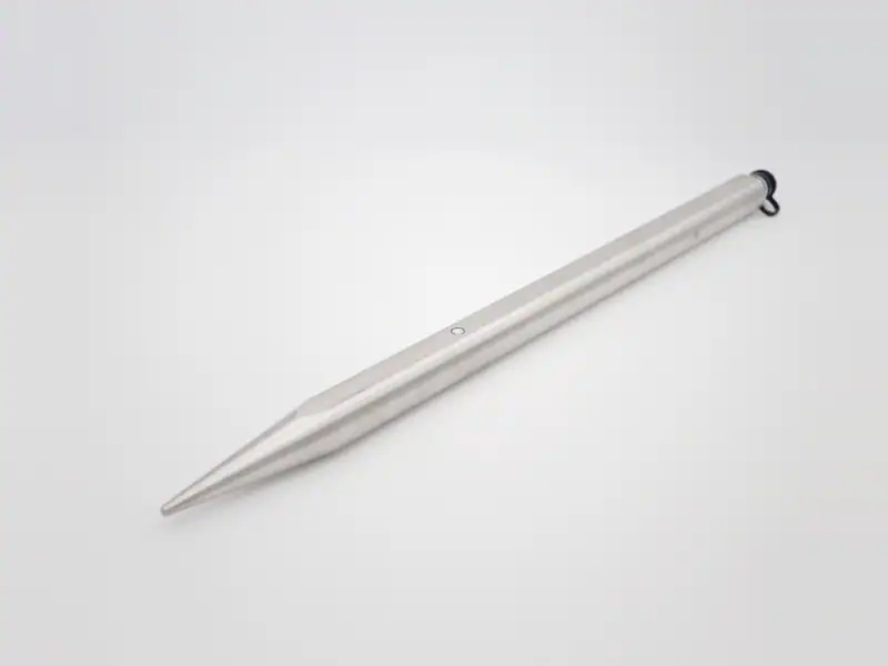
What a Free-Field Pressure Sensor Is
A free-field pressure sensor measures a pressure wave travelling through air or water without being mounted to a wall, manifold, or pressure tap. The sensor sits in the path of the wave on a slim probe, and the wave passes over the sensing diaphragm rather than reflecting off a structure. That is the only way to record the true incident wavefront in an outdoor blast or shock test — any wall-mount adds reflection and structural ringing that distort the signal.
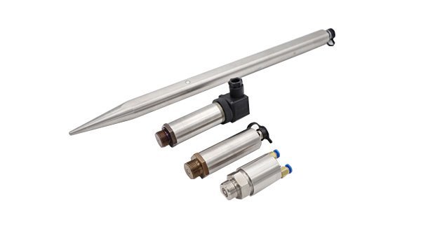
The CYG411 is the medium-pressure variant of the CYG400 piezoresistive dynamic pressure family. The probe is a streamlined teardrop, Φ6.5 mm at the head and 406 mm long. Two design choices keep distortion low: the form factor is slender enough that the probe barely perturbs the incoming wave, and the diaphragm sits flush with the probe surface in a cavity-less mount, so there is no internal acoustic resonance to corrupt the rising edge.
Five ranges from 1 MPa to 10 MPa cover the mid-amplitude band of outdoor blast measurement — the regime of confined medium-pressure blast, driver-tube shock, and mid-field detonation studies. Above 1 MPa, switch to the CYG411 medium-pressure free-field; above 20 MPa, the CYG412.
CYG411 Technical Specifications
| Group | Parameter | Value |
|---|---|---|
| Sensing | Technology | MEMS piezoresistive silicon strain bridge |
| Diaphragm | Stainless steel, fully flush, cavity-less | |
| Anti-light interference | Anti-IR plus visible-light optical protection (option F4) | |
| Range & Speed | Range span | 1 / 2 / 3.4 / 6 / 10 MPa |
| Natural frequency | 180 / 240 / 280 / 320 / 360 kHz (range-matched) | |
| Rise time | 1 µs (1–3.4 MPa); 0.5 µs (6–10 MPa) | |
| Accuracy | Sensor accuracy | 0.25% / 0.5% FS |
| Non-linearity | ±0.2% to ±0.5% FS | |
| Zero drift | 0.15 mV / 8 h or 0.2 mV / 8 h | |
| Zero-point temperature coefficient | 0.03% / 0.05% FS/°C | |
| Sensitivity temperature coefficient | 0.03% / 0.05% FS/°C | |
| Power & Output | Power | Sensor: 1 mA or 1.5 mA constant current, or 12 VDC constant voltage. CYG1410 transmitter variant: ±15 VDC, or 12–24 VDC |
| Output | Differential mV signal (sensor); 0–5 V amplified standard signal (CYG1410 transmitter variant) | |
| Mechanical | Probe form | Streamlined teardrop, Φ6.5 mm head × Φ6 mm body × 406 mm length |
| Mounting thread | M20×1.5 | |
| Wetted material | Silicon + stainless steel; non-corrosive media | |
| Environment | Operating temp | -40 to +85°C standard; -55 to +125°C extended |
| Compensation temp | 0 to +70°C (custom ranges available on request) | |
| Transient peak temp | +2000°C / 20 ms (with optional protective measures) |
Range Selection: Five Models, One Probe Form
The CYG411 ships with five pre-defined ranges. The probe geometry, mounting thread, and rise time are identical across all five — only the sensing element is range-matched. Pick the range whose full-scale value sits ~30-50% above the expected peak amplitude of your event, so you keep both headroom and bridge sensitivity.
| Range | Natural frequency | Rise time | Typical event |
|---|---|---|---|
| 0–1 MPa | 180 kHz | 1 µs | Near-field detonation, driver-tube medium-pressure shock |
| 0–2 MPa | 240 kHz | 1 µs | Confined-charge blast, ballistic chamber wavefront |
| 0–3.4 MPa | 280 kHz | 1 µs | High-explosive close-in, shaped-charge research |
| 0–6 MPa | 320 kHz | 0.5 µs | Strong reflected shock, internal-blast loading |
| 0–10 MPa | 360 kHz | 0.5 µs | Peak medium-pressure detonation, energetic-materials test |
The 6 MPa and 10 MPa ranges step the natural frequency up to 320 and 360 kHz and tighten the rise time to 0.5 µs, so the rising edge captures the fastest mid-pressure transients. If your event peaks above 10 MPa, step up to CYG412.
Where the CYG411 Is Used
The 300-800 kPa low-pressure free-field band (the cased-mount counterpart for indoor / fluid-contained measurement in the same pressure range is the CYG405) corresponds to a specific class of events — moderate-energy outdoor pressure waves where amplitude is well below 1 MPa but rising edge is still in the microsecond regime.
Outdoor Blast Wavefront
Mid-field detonation pressure profiles and free-air shockwave studies where the probe sits at a moderate standoff, with peaks in the low-MPa range.
Industrial-Explosion Safety
Gas-deflagration and vented-vessel testing, dust-explosion characterization, and vent-panel work where peak pressures run roughly 1 to 6 MPa.
Structural-Loading Tests
Reflected-pressure measurements on wall panels, blast-loading on civil structures, soil-shock studies in instrumented test arenas.
Shock-Tube Research
University and lab shock tubes operating in the MPa range — characterizing diaphragm-rupture profiles, wave fidelity, and gas-dynamic transients.
Ballistic-Gel & Medical
Blast-injury research in ballistic gelatin or tissue surrogate, where transmitted peak pressure reaches the low-MPa range with sub-millisecond rise.
Energetic-Materials Screening
Propellant and pyrotechnic characterization where peak output runs 1 to 10 MPa and the arena allows free-field probe placement.
Installation: Probe Orientation and Mounting
A free-field probe gives a clean reading only when it is oriented and supported correctly. Three rules cover most outdoor blast installations.
Wave alignment. Point the Φ6.5 mm head end toward the source. The streamlined teardrop is shaped so that the wavefront hits the head perpendicular to the diaphragm and the shaft trails away — that minimizes diffraction and reflection at the diaphragm. Off-axis placement of more than ~15° introduces angle-dependent error in peak amplitude.
Mount support. Use a ground stake, a wave-aligned tripod, or a mast clamp at the probe’s threaded mid-section. Clamp on the M20×1.5 thread, not on the probe shaft — clamping on the shaft adds bending mode to the probe and corrupts the rising edge with mechanical resonance. Keep the cable run away from the line-of-sight to the source.
Standoff distance. Place the probe at the radial distance you want to characterize. For repeatability, fix the probe-to-source distance precisely and record it with the test — pressure scales steeply with distance in the near-to-mid field, so a 10% distance error becomes a 20-30% pressure error. The 406 mm probe length lets you mount the support far enough behind the head that the support structure does not interfere with the wave.
CYG411 Ordering Code
The CYG411 sensor and its CYG1410 transmitter sibling share the same selection scheme. Pick the model first, then walk down the segments. Sensor variants use S4 / S7 (mV out); the CYG1410 transmitter variant uses S11–S14 (0–5 V amplified out).
CYG <410 / 1410> (range) <accuracy> <power+output> <cable> <mount> <anti-IR> <custom>
| Segment | Code | Meaning |
|---|---|---|
| Model | 410 / 1410 | Sensor (mV out) or CYG1410 transmitter (0–5 V amplified) |
| Range | 1 / 2 / 3.4 / 6 / 10 | Full-scale value in MPa |
| Accuracy | P3 | 0.25% FS |
| P4 | 0.5% FS | |
| P5 | 1.0% FS (CYG1410 transmitter only) | |
| Power + Output | S4 | mV out / 1 mA or 1.5 mA constant current (sensor) |
| S7 | mV out / 12 VDC constant voltage (sensor) | |
| S11 | 0–5 V / 12–24 VDC / 120 kHz BW (CYG1410) | |
| S12 | 0–5 V / ±12 VDC or ±15 VDC (CYG1410) | |
| S13 | 0–5 V / ±12 VDC or ±15 VDC / 100 kHz BW (CYG1410) | |
| S14 | 0–5 V / ±12 VDC or ±15 VDC / 200 kHz BW (CYG1410) | |
| Cable / Output | C1 | Direct lead |
| C2 | Aviation connector | |
| C3 | Round connector | |
| C4 | IP68 waterproof box exit | |
| Mount | A1 | M20×1.5 (standard) |
| A6 | User-defined thread | |
| Anti-IR | F4 | Anti-IR plus visible-light optical protection |
| Custom | Q | Custom selection sheet (special temperature, custom thread, etc.) |
Worked example (sensor): CYG 410 (0–500 kPa) P3 S4 C2 A1 F4 Q — sensor variant, 0–500 kPa range, 0.25% accuracy, mV output on 1 mA constant current, aviation connector, M20×1.5 standard mount, anti-IR optical, custom selection sheet attached.
Worked example (transmitter): CYG 1410 (0–500 kPa) P4 S12 C4 A1 F4 Q — CYG1410 transmitter variant, 0–500 kPa range, 0.5% accuracy, 0–5 V output on ±15 VDC, IP68 waterproof connector, M20×1.5, anti-IR optical, custom sheet.
CYG411 FAQ
Technical Support
Three background guides for engineers specifying or commissioning a CYG411 free-field probe. Open in a new tab; the deep-dives complement the spec-and-selection focus of this page.
Ready to Specify a CYG411?
Send us the expected peak amplitude, the radial distance to the source, the ambient temperature range, and whether near-field IR flash is in play. Our pressure-instrument engineers will reply with a CYG411 range, ordering code, and lead time.
Our engineers typically respond within 12 business hours with detailed technical specifications.