Bubbler Level Measurement: How It Works & When to Use It
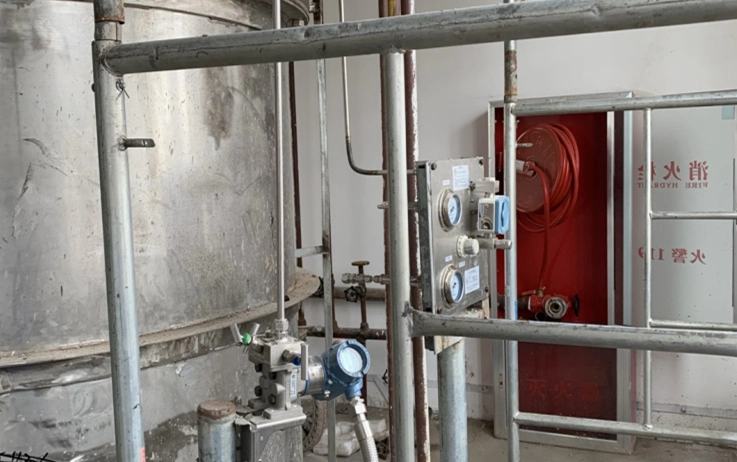
When the liquid in your tank is corrosive, slurry-laden, or prone to crystallising on a sensor face, putting a transmitter diaphragm in direct contact is asking for a failed instrument. A bubbler sidesteps that by keeping the sensor out of the tank entirely: you meter a slow stream of gas down a dip tube, and the back-pressure the gas must overcome tells you how much liquid sits above the tip. It is an old technique, but on the dirtiest service it still outlasts newer alternatives. This all applies to industrial process tanks; the same idea also serves environmental water-level and open-channel flow, though the hardware there is its own topic.
How a bubbler measures level
A bubbler answers one question: how deep is the liquid above a fixed point near the tank bottom? You run a small, steady flow of purge gas (instrument air or nitrogen) down a dip tube whose open end sits low in the vessel. Gas pressure inside the tube climbs until it just exceeds the hydrostatic head of liquid at the tube tip, at which point bubbles escape. Hold the flow low and steady, and the pressure in the tube settles at very nearly the head pressure of the liquid above the tip. A pressure transmitter plumbed into the tube line reads that back-pressure, and because head is proportional to level, the reading tracks level directly.
The whole advantage is that the transmitter never touches the process. Only the dip tube does, and you can make a dip tube from whatever material survives the fluid: PTFE, tantalum, Hastelloy, or a plain length of pipe. That one fact is why bubblers persist in acid tanks, lime-slurry sumps, and plating baths long after every “smarter” technology has come and gone.
The hydrostatic math, with a worked example
The back-pressure a bubbler reads is pure hydrostatics: P = ρ · g · h, where ρ is the liquid density, g is 9.81 m/s², and h is the height of liquid above the dip-tube tip. Get ρ right and the rest is arithmetic.
Take a dilute sulphuric-acid tank with a working density near 1100 kg/m³ and a maximum liquid height of 2.0 m above the tube tip. Pull ρ from a reference source such as the NIST fluid-property data rather than a nameplate, because a wrong density feeds straight into the level error. At full tank:
P = 1100 × 9.81 × 2.0 = 21,582 Pa ≈ 21.6 kPa (about 3.13 psi).
So the transmitter never sees more than roughly 21.6 kPa from level. Size it to a low gauge span, for example 0–30 kPa, which leaves sensible headroom without wasting resolution on a 0–100 kPa range you will never fill. The HM20 general-purpose transmitter reaches down to a 0–5 kPa span and up through 100 MPa, so a 0–30 kPa build sits well inside its range and gives you a 2× overpressure margin as standard.
One caution trips people up: the reading follows density, not level alone. If fluid concentration (and therefore ρ) drifts, the level reading drifts with it. This is not a small effect. On coal-fired flue-gas desulphurisation absorbers, where a limestone-gypsum slurry swirls and entrains gas, plant instrumentation reports document level errors of 1–2 m when the reading leans on density compensation alone, enough to risk overflowing the tower. Where density moves, plan to re-range or add a dedicated density measurement rather than trust one calibration.
Building the purge line: air source, restrictor, dip tube
A bubbler is only as good as its purge control. The job is to deliver a flow low enough that the gas velocity in the tube adds no measurable pressure drop of its own, yet high enough that the tube never floods or clogs. In practice that means a few bubbles per second, no more.
Three parts do the work. First, a clean, dry, regulated gas supply — instrument air on most plants, nitrogen where the vapour space is flammable or where air would react with the process. Second, a flow element: either a constant-differential regulator or a simple needle valve and purge rotameter that you set once. A constant-flow design holds the bubble rate steady as level changes, which is what you want; a bare needle valve lets the bubble rate sag as head rises, so reserve it for shallow tanks. Third, the dip tube itself. Size the bore generously, a common choice being 12–25 mm, so surface tension and minor fouling cannot choke it. Set the tip above the sludge line, not on the floor, so settled solids never bury the opening.
Why does bubble rate matter so much? Push too much gas and the friction of gas moving down the tube adds to the measured pressure, and your level reads high. Starve the flow and the tube can back-fill or plug. The “few bubbles per second” rule is the sweet spot where friction is negligible and the tube stays clear.
Open tanks versus closed tanks: gauge or DP hookup
The tank’s pressure reference decides which transmitter you need, and this is where most bubbler installs go wrong.
On an open or vented tank, the vapour space sits at atmosphere, so the dip-tube back-pressure references atmosphere for free. A gauge transmitter is all you need; connect it to the bubbler tube and you are done. An HM20 in a low gauge span fits this case directly.
On a closed or pressurised tank, the vessel pressure adds to the bubbler back-pressure, and a gauge transmitter would read level plus tank pressure and be useless. Here you switch to a differential-pressure transmitter. Pipe the dip-tube back-pressure to the high side, and tie the low side to the tank’s vapour space: a dry leg on clean gas, a filled wet leg where the vapour condenses or fouls. The DP cell then subtracts tank pressure and reads level alone. The HM31 differential transmitter measures spans from 0–10 kPa up to 2 MPa and tolerates line (static) pressure to 20 MPa. That covers the low differential a bubbler produces on a pressurised vessel. Its static-pressure effect is ±0.05% FS per 100 kPa, the number to check when the tank runs at pressure. For a deeper look at that hookup, see our guide to DP transmitter level measurement.
When a bubbler is the right call
A bubbler earns its place on dirty and aggressive service, but it is not a default. In the field on lime-slurry and neutralisation tanks, we commission bubblers precisely because the alternatives foul within weeks and a dip tube does not. Use the table below before you commit.
| Condition | Bubbler fit | Better alternative |
|---|---|---|
| Corrosive / abrasive / crystallising media | Strong — only an inert tube is wetted | — |
| Solids-laden or settling slurry | Strong — tip set above sludge line | — |
| Reliable instrument-air or N₂ on site | Required | If absent, submersible or sealed DP |
| Fast level changes / tight response | Weak — purge line adds lag | Submersible HM21 or direct DP |
| Foaming or violently agitated surface | Weak — reading scatters | Guided-wave radar |
| Nothing may enter the tank | Not applicable | Non-contact radar |
Choose a bubbler when the media is corrosive, viscous, crystallising, or solids-laden, when you want zero wetted electronics, and when a continuous purge-gas supply already exists on site. Flue-gas desulphurisation absorber slurry, water-treatment lime-slurry and neutralisation tanks, plating baths, and pulp stock chests are classic wins, and ISA guidance on level-instrument selection points the same way for aggressive service.
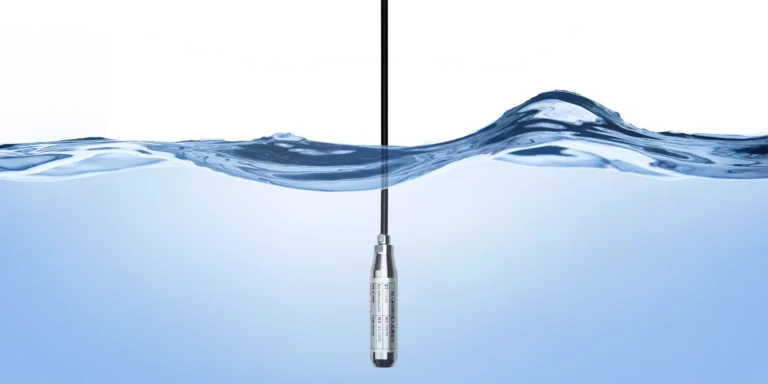
Look elsewhere when the response must be fast, since the purge line adds lag; when there is no dependable air or nitrogen; or when the surface foams. In those cases a submersible hydrostatic transmitter such as the HM21, dropped straight into the liquid, or a direct diaphragm-seal DP transmitter is simpler, and a non-contact radar suits tanks where nothing should enter. Our submersible level transmitter guide covers that immersed alternative. For custody-grade tank gauging in oil & gas, API tank-measurement practice usually drives the method choice instead. The bubbler wins on chemistry and simplicity; it loses on speed and on any site without a purge supply.
Bubbler-ready level transmitters from HMK TECH
Once you settle the hookup, the transmitter choice follows three questions: open or closed tank, how corrosive the wetted path is, and what span your worked head demands.
| Tank / service | Transmitter | Verified range |
|---|---|---|
| Open / vented, benign purge path | HM20 gauge | −100 kPa … 0–5 kPa … 100 MPa; 2× overpressure |
| Closed / pressurised | HM31 differential | DP 0–10 kPa … 2 MPa; static ≤ 20 MPa |
| Corrosive wetted path | HM50 (tantalum diaphragm) | −100 kPa … 0–5 kPa … 60 MPa; ±0.25% FS |
For an open tank with a benign purge path, a general-purpose gauge unit is the economical pick. Range the HM20 to your calculated head — the 0–30 kPa build from the worked example — with a 4–20 mA output into the DCS. For a closed or pressurised tank, move to the HM31 differential transmitter with the dip tube on the high side and a reference leg on the vapour space. Where the purge gas or the shared wetted parts contact a strongly corrosive vapour, specify a corrosion-resistant front end. The HM50 uses a tantalum diaphragm with a PVC, titanium, or PTFE housing you select against the medium. It holds ±0.25% FS and covers low spans from 0–5 kPa upward. Confirm the wetted material against your actual fluid before you order, and note the medium on the purchase order so we match the diaphragm and housing to it.
The bottom line is three calls. On an open corrosive tank, spec a bubbler with a low-range HM20 gauge transmitter sized to your worst-case head. On a pressurised tank, switch to an HM31 DP transmitter with the dip tube on the high side and a reference leg on the vapour space. And reach for the HM50 tantalum front end whenever the wetted path sees aggressive chemistry.
Frequently Asked Questions
How do you calculate level from a bubbler system?
Level equals the measured back-pressure divided by density times gravity: h = P / (ρ · g). Read the tube back-pressure on the transmitter, divide by ρg for your fluid, and you have the height above the dip-tube tip. Remember the result scales with density, so a change in concentration shifts the reading.
What gas is used in a bubbler level system?
Clean, dry instrument air on most plants. Where the vapour space is flammable, or where air would oxidise or react with the process, use nitrogen instead. The gas must be dry and oil-free so it does not foul the tube.
Can a bubbler be used on a pressurised (closed) tank?
Yes, but not with a gauge transmitter. Use a differential-pressure transmitter with the dip-tube back-pressure on the high side and the tank vapour space on the low side, so the cell subtracts tank pressure and reads level alone.
What are the disadvantages of a bubbler system?
It needs a continuous purge-gas supply, it responds slowly because of the gas line, its accuracy depends on stable fluid density, and it can read high if the bubble rate is set too fast. Foaming or violently agitated surfaces also degrade the reading.
Bubbler versus submersible level transmitter — which is better?
A submersible transmitter is simpler and faster when the fluid is clean enough to immerse a sensor. A bubbler is better when the fluid is corrosive, abrasive, or plugging, because only an inert dip tube touches the process. Match the method to the chemistry.
How many bubbles per second should a bubbler produce?
A few per second is the target. That is fast enough to keep the tube clear and slow enough that gas friction in the tube adds no measurable error. Setting it much higher makes the level read high.