4-20 mA Loop Resistance & Power-Supply Calculator
Check whether your supply can drive the transmitter plus its load at 20 mA — and how much resistance you can still add.
Every 2-wire 4-20 mA loop has a voltage budget. The supply has to power the transmitter and still push 20 mA through the sense resistor, the wiring, and anything else in series. When the budget runs out, the loop reads fine at low pressure and then clamps or goes erratic near full scale. This calculator turns that budget into one number: the maximum loop resistance your supply can carry, and whether your present loop passes.
How the calculation works
The current loop runs at a constant 4-20 mA, so the worst case for voltage is always the top of the range, 20 mA. At that point the burden takes the most voltage, and the transmitter still needs its minimum to operate. The headroom equation is simple:
Maximum loop resistance = (Vsupply − Vmin) ÷ 0.020 A
Subtract the transmitter’s minimum operating voltage from the supply, then divide the leftover volts by 20 mA. That gives the largest total resistance the loop can carry before the transmitter is starved. Compare it to the resistance you actually have, and the gap is your headroom. If the headroom is negative, the loop will fail near 20 mA even though it looks healthy at 4 mA.
What counts as loop burden
The burden is everything in series with the current, added together. Miss one and the number is wrong:
| Element | Typical value | Note |
|---|---|---|
| Sense / load resistor | 250 Ω | Often the DCS or PLC input; 250 Ω is the HART minimum. |
| Wiring (both conductors) | varies | Count the full out-and-back length, not one way. |
| Intrinsic-safety barrier | tens to hundreds of Ω | Adds series resistance and its own end-to-end voltage drop. |
| Series indicators / recorders | 10–100 Ω | Each loop-powered meter spends part of the budget. |
A worked example
Take a common bench: a 24 V supply, a transmitter that needs 12 V to operate, and a 250 Ω sense resistor with nothing else in series. The available voltage is 24 − 12 = 12 V, so the maximum loop resistance is 12 ÷ 0.020 = 600 Ω. The present burden is only 250 Ω, which needs 0.020 × 250 = 5 V at 20 mA, leaving 7 V of headroom. The loop passes, and you can still add about 350 Ω of barrier, indicators, or cable before it fails. If the same loop ran on an 18 V supply, the ceiling would drop to (18 − 12) ÷ 0.020 = 300 Ω, and that 250 Ω resistor would leave only 1 V to spare.
Field pitfalls the formula will not catch
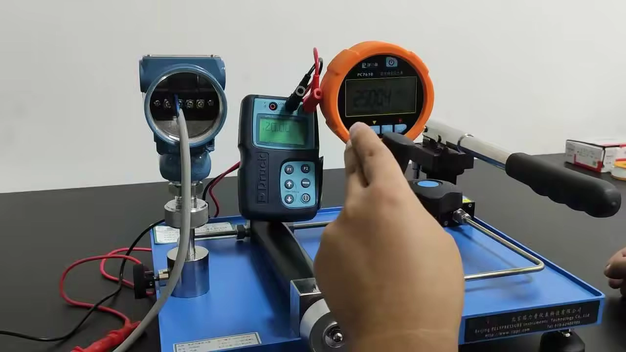
Measure the supply under load, not on the bench
A 24 V supply that sags to 21 V when the loop draws current quietly removes 3 V of budget. Measure it powering the real loop, and measure the transmitter’s terminal voltage directly rather than trusting the panel reading.
HART needs at least 250 Ω
If the loop carries HART, the resistance is not just a budget item, it is a requirement: the modem needs 250 Ω minimum to develop a readable signal. Cutting the resistor to save voltage can kill HART communication.
Use the transmitter’s real minimum voltage
Datasheets quote a minimum operating voltage, and it is often higher than people assume, especially on smart or display models. Use the figure for your model, not a round 10 V.
Cable is two conductors
Loop resistance is the out-and-back path, so a 500 m run of 18 AWG is 1,000 m of copper. On long runs that resistance is a real slice of the budget, which is why the calculator counts both conductors.
If a loop that should pass still misbehaves, the fault has usually moved from the budget to the hardware. Our pressure transducer troubleshooting guide works through a wrong reading by symptom, and the 4-20 mA signal calculator converts the current you measure into engineering units. When that loop carries an orifice-flow signal, the DP flow calculator turns its differential pressure into flow. For the transmitters themselves, see the HMK pressure transducer range.
Frequently Asked Questions
What is the maximum loop resistance for a 4-20 mA transmitter?
It is the available voltage divided by 20 mA: (supply voltage minus the transmitter’s minimum operating voltage) ÷ 0.020 A. On a 24 V supply with a 12 V transmitter that is 600 Ω total, shared between the sense resistor, wiring, and any barriers.
Why does my loop work at 4 mA but fail near 20 mA?
Because voltage across the burden rises with current. At 4 mA the burden takes little voltage; at 20 mA it takes five times as much, and if the budget is tight the transmitter drops below its minimum and the reading clamps or jumps.
Does the load resistor have to be 250 ohms?
No, unless the loop uses HART, which needs 250 Ω minimum. Otherwise the resistor only has to give the receiver a usable voltage while staying inside the loop’s resistance ceiling.
How do I find cable resistance?
Multiply the per-metre resistance of the wire gauge by the full loop length, both conductors. The AWG helper in the calculator does this once you enter the one-way run length.
Recommended Pressure Transducers
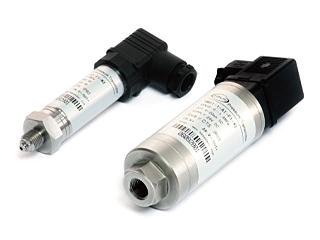
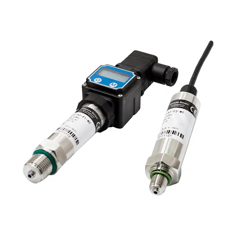 HM20General-Purpose TransmitterSteady 4-20 mA service with low loop burden.
 HM25Industrial TransmitterRugged for spike-prone or cycling duty.
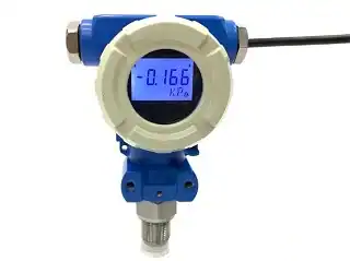
 HM29Digital / HART TransmitterOn-board diagnostics flag loop faults early.
Related Reading
 Pressure Transducer TroubleshootingDiagnose a wrong reading by symptom.
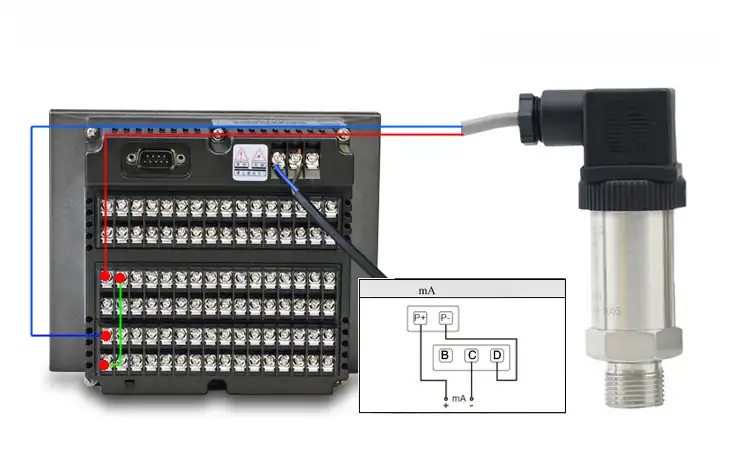 4-20 mA Wiring: 2-, 3- and 4-WireTerminations for each loop type.
 Pressure Transmitter CalibrationThe zero-and-span procedure, step by step.
Specifying transmitters for a long or barrier-heavy loop?
Tell us the supply, cable run, and what is in series, and we will confirm the right HMK pressure transducer and the loop budget it needs.